
Method and apparatus for providing peak detection circuitry for data communication systems

a data communication system and peak detection technology, applied in the field of communication systems, can solve the problems of affecting the delicate electrometer and the analog circuitry of the transmitter unit of the monitoring system, affecting the processing of detected signals, so as to achieve low cost and low noise, effective and low noise approach

Active Publication Date: 2010-03-16
ABBOTT DIABETES CARE INC
View PDF820 Cites 20 Cited by
  • Summary
  • Abstract
  • Description
  • Claims
  • Application Information

AI Technical Summary

Benefits of technology

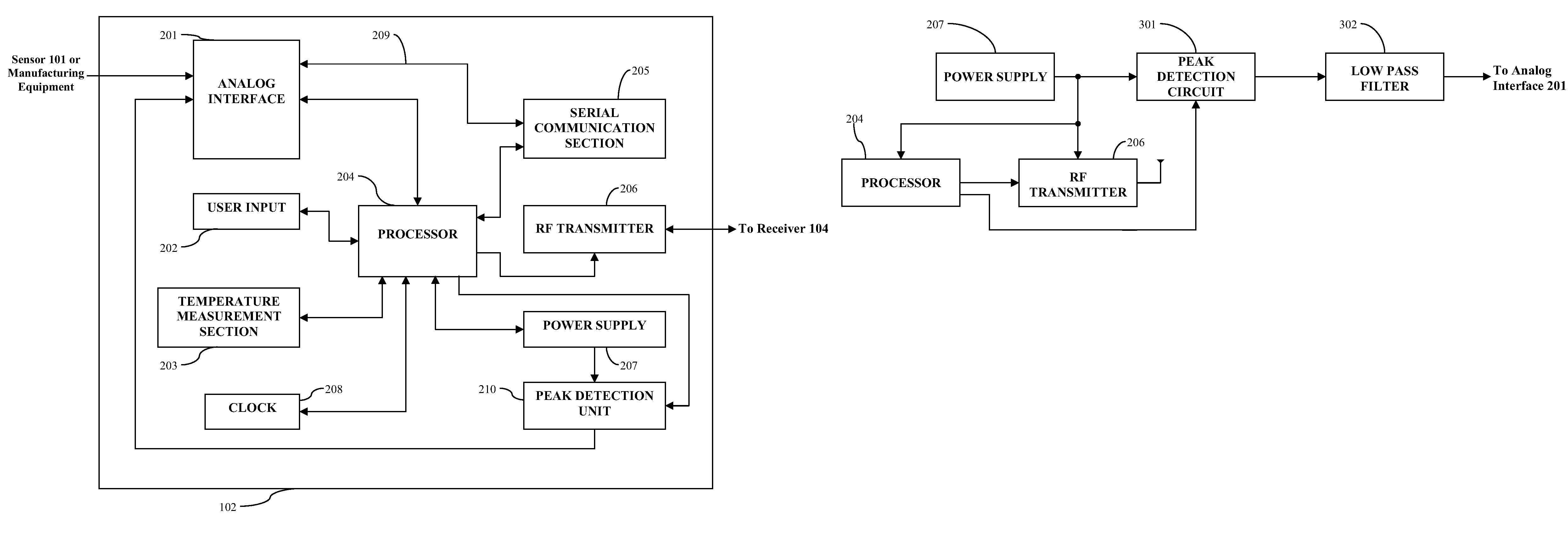
[0024]Accordingly, in accordance with the various embodiments of the present invention, by using a peak detection circuit with a tuned low pass filter, an effective, low cost and low noise approach to isolating the battery droop, even that in excess of 0.5 volts, may be achieved such that in the monitoring system discussed above, the detected and processed data values are not substantially effected, and the delicate analog circuitry of the transmitter is not adversely effected by the fluctuation in power supply signal.INCORPORATION BY REFERENCE

Problems solved by technology

This, in turn, may have a negative impact on the processing of detected signals such as by signal degradation or data loss, and importantly, may adversely affect the delicate electrometer and the analog circuitry in the transmitter unit of the monitoring system.
More specifically, when the analog front end circuitry in the transmitter of the monitoring system is disturbed, there may be a several second delay when the data may be unusable and a longer delay (for example, on the order of 10 seconds) when the data may be unreliable or beyond the tolerance range of desired accuracy.

Method used


Image

  • Method and apparatus for providing peak detection circuitry for data communication systems
  • Method and apparatus for providing peak detection circuitry for data communication systems
  • Method and apparatus for providing peak detection circuitry for data communication systems

Examples


Embodiment Construction

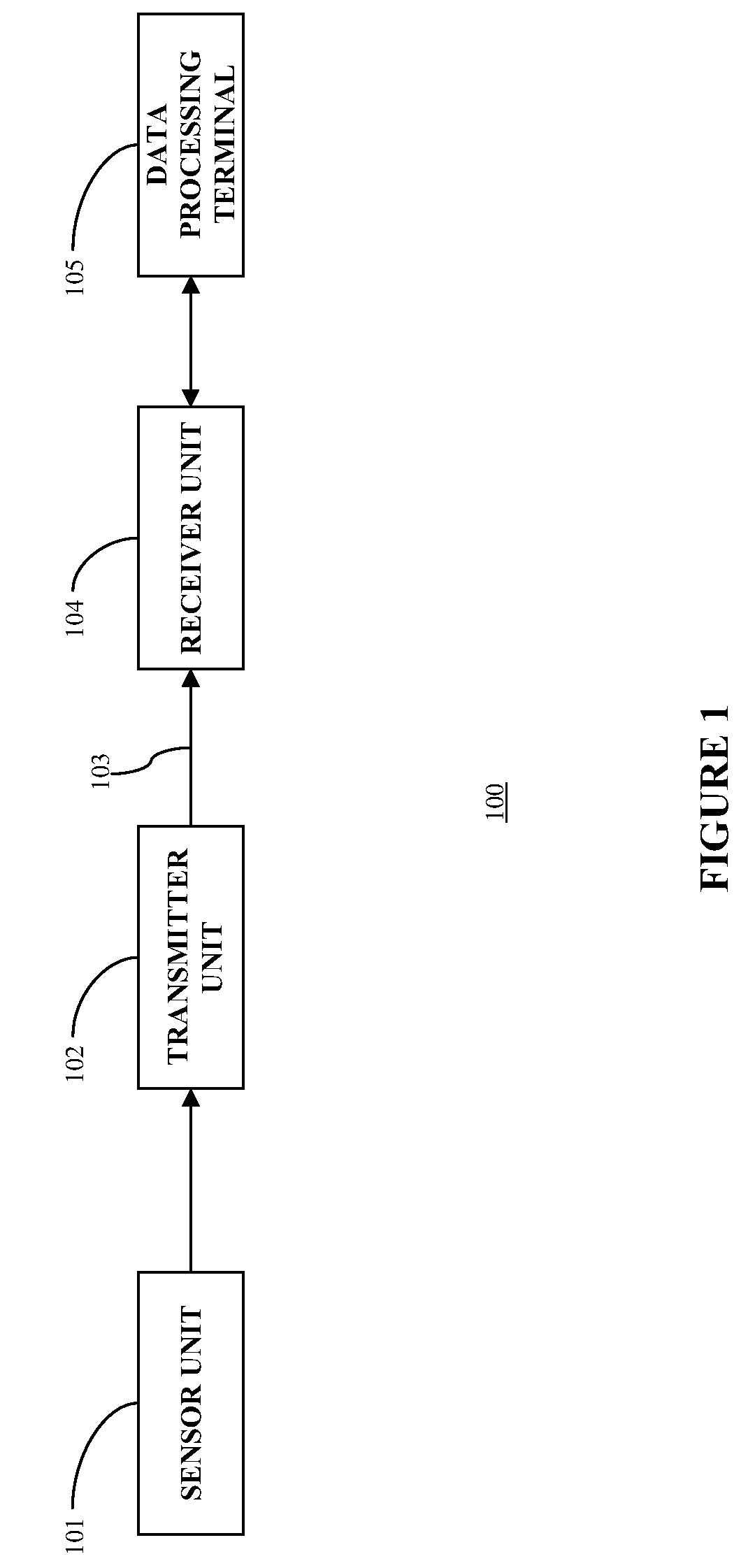
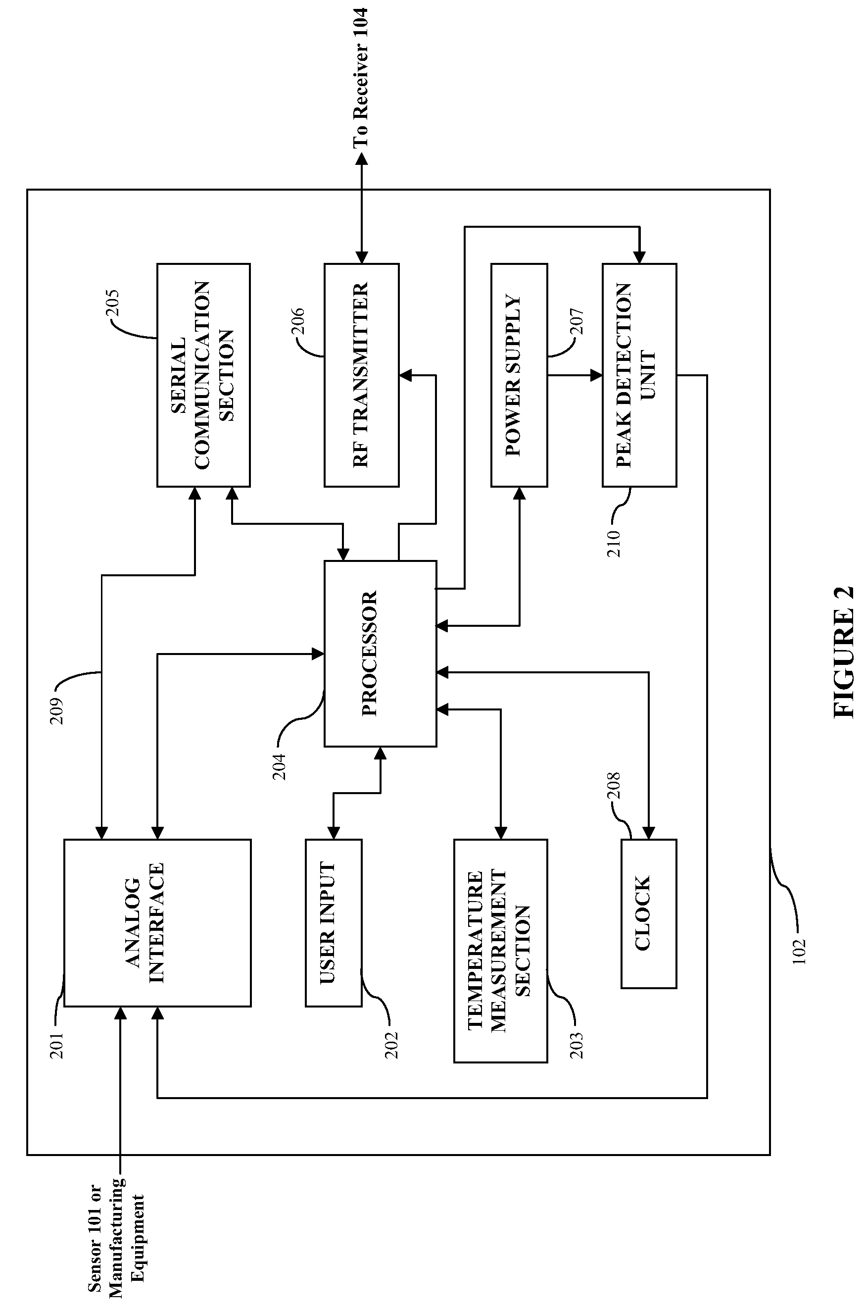
[0032]FIG. 1 illustrates a data communication system such as, for example, a continuous glucose monitoring system 100 in accordance with one embodiment of the present invention. In such an embodiment, the continuous glucose monitoring system 100 includes a sensor 101, a transmitter 102 coupled to the sensor 101, and a receiver 104 which is configured to communicate with the transmitter 102 via a communication link 103. The receiver 104 may be further configured to transmit data to a data processing terminal 105 for evaluating the data received by the receiver 104. Only one sensor 101, transmitter 102, communication link 103, receiver 104, and data processing terminal 105 are shown in the embodiment of the continuous glucose monitoring system 100 illustrated in FIG. 1. However, it will be appreciated by one of ordinary skill in the art that the continuous glucose monitoring system 100 may include one or more sensor 101, transmitter 102, communication link 103, receiver 104, and data ...


PUM


Abstract

Method and apparatus for providing a peak detection circuit comprising a diode including an input terminal and an output terminal the input terminal of the diode configured to receive an input signal, a capacitor operatively coupled to the output terminal of the diode, an output terminal operatively coupled to the capacitor and the output terminal of the diode for outputting an output signal is provided. Other equivalent switching configuration is further provided to effectively detect and compensate for a voltage droop from a power supply signal, as well as to electrically isolate the voltage droop from the system circuitry.

Description

RELATED APPLICATION[0001]This application claims priority under 35 USC §119(e) to Application No. 60 / 466,243 filed Apr. 28, 2003 entitled “Method and Apparatus for Providing Peak Detection Circuitry for Data Communication Systems” and assigned to TheraSense, Inc., assignee of the present application, and the disclosure of which is incorporated herein by reference for all purposes.BACKGROUND[0002]The present invention relates to communication systems. More specifically, the present invention relates to radio frequency (RF) communication systems for data communication between portable electronic devices such as in continuous glucose monitoring systems.[0003]Continuous glucose monitoring systems generally include a small, lightweight battery powered and microprocessor controlled system which is configured to detect signals proportional to the corresponding measured glucose levels using an electrometer, and RF signals to transmit the collected data. When the microprocessor is active or ...

Claims


Application Information

Patent Timeline
Patent Type & Authority Patents(United States)
IPC IPC(8): H03K5/153
CPCA61B5/0002A61B5/14532G01D4/00A61B2560/0214A61B2560/0252G06F19/3418G16H40/67
Inventor REGGIARDO, CHRISTOPHER V.
Owner ABBOTT DIABETES CARE INC
Learn More