Apparatus for measuring a turbine blade

a technology for measuring apparatus and turbine blades, which is applied in the direction of mechanical measuring arrangements, machines/engines, instruments, etc., can solve the problems of turbine blades, especially the last stage turbine blades, experiencing water droplet erosion, and jagged edges along the leading edge of the turbine blad

Inactive Publication Date: 2010-03-23
GENERAL ELECTRIC CO
View PDF21 Cites 9 Cited by
  • Summary
  • Abstract
  • Description
  • Claims
  • Application Information

AI Technical Summary

Problems solved by technology

During operation, turbine blades, particularly the last stage turbine blades in a steam turbine, experience water droplet erosion due to their location in the steam path.
Over time, this erosion produces a jagged edge along the leading edge of the turbine blade.
This results in increased stress concentrations and, ultimately, may cause a failure in the turbine blade.
In extreme cases, if the correct loading and eroding conditions coexist, the entire tip of the turbine blade may break free, which will cause significant damage to the turbine.
However, the constraints related to taking the necessary measurements of the turbine blade chord length are considerable.
First, in general, downtime for turbine power generators is limited, which means there is limited opportunity to take the necessary measurements.
This issue is exacerbated by the number of turbine blade measurements required to accurately ascertain the erosion level of a set of turbine blades.
Second, because disassembling the turbine would be too time consuming and costly, the measurements must be taken with the turbine in the assembled condition, i.e., with the turbine blades assembled on the rotor within the turbine.
Access to the assembled turbine blades to take the necessary measurements is difficult and limited.
However, current processes for obtaining the measurements are lengthy, inefficient and result in wasted man-hours and increased downtime to the turbine unit.
Further, current devices and methods do not yield accurate or reliable data.

Method used


Image

  • Apparatus for measuring a turbine blade
  • Apparatus for measuring a turbine blade
  • Apparatus for measuring a turbine blade

Examples


Embodiment Construction

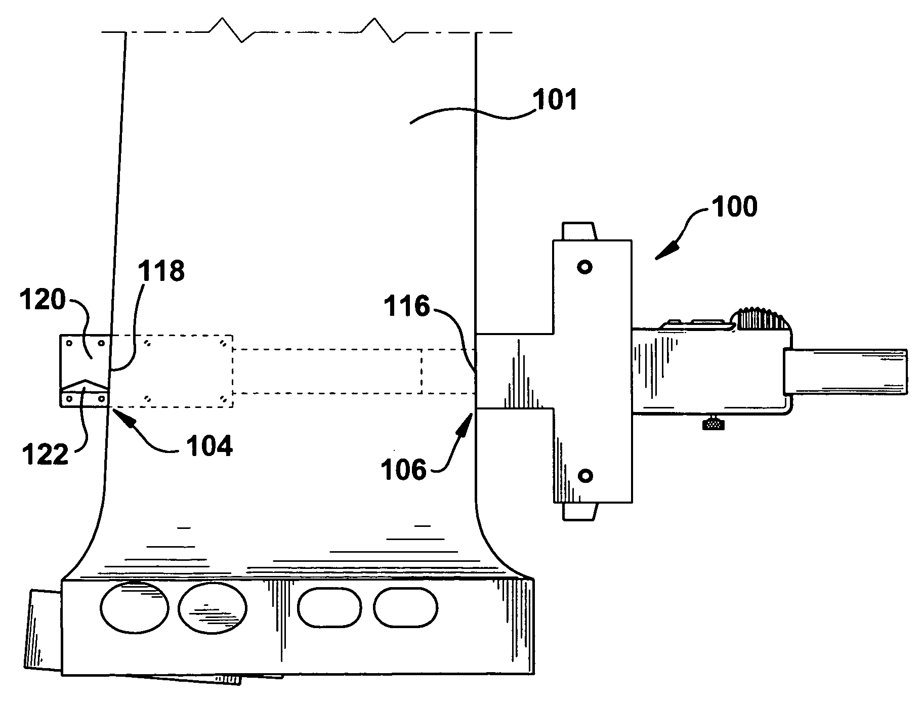
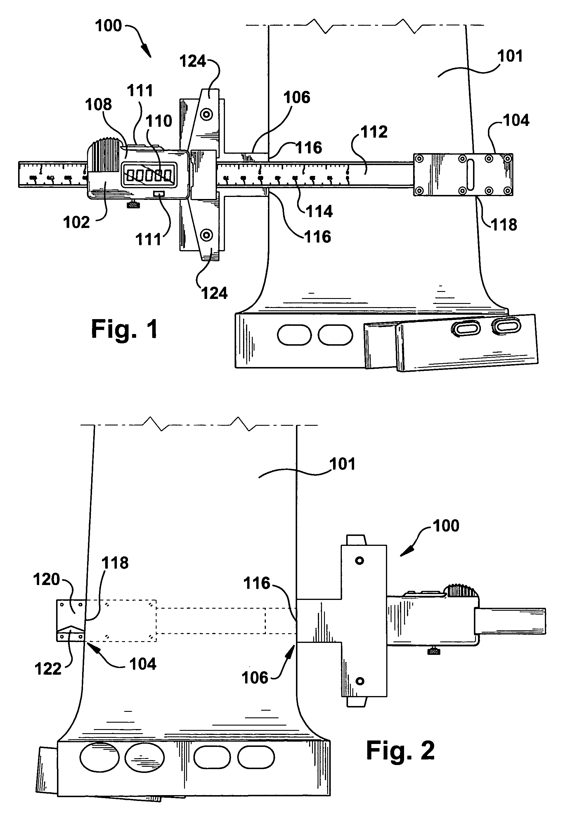
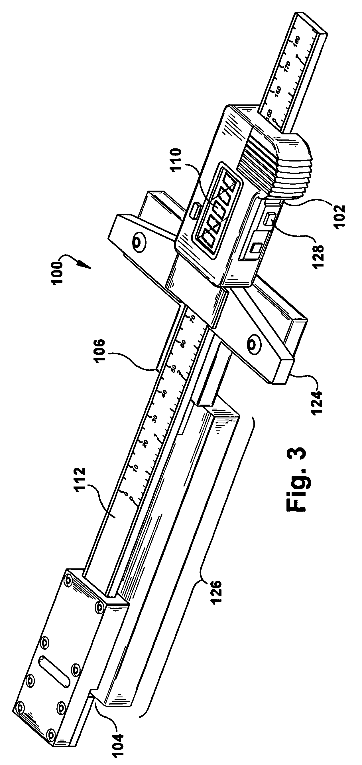
[0021]Referring now to the figures, where the various numbers represent like parts throughout the several views, FIG. 1 illustrates a top view of an erosion gauge 100 according to an exemplary embodiment of the present application. As shown, the erosion gauge 100 is aligned against a turbine blade 101 such that the erosion gauge 100 may take a measurement of the chord length of the turbine blade 101. (Note that the present invention is discussed primarily in relation to taking measurements of eroded turbine blades. As one of ordinary skill in the art would appreciate, the present invention is not so limited and may be used to take other similar types of measurements.) The erosion gauge 100 may include a digital readout scale or an electronic depth gauge 102, which may measure the distance between a lower jaw 104 and an upper jaw 106. In other embodiments, a dial gage or DRO scale may be used. The electronic depth gauge 102 may include an interface 108 with a display 110 for displayi...


PUM


Abstract

An erosion gauge for measuring a chord length of an eroded turbine blade in a steam turbine that may include: a jaw that includes a lower jaw that includes a lower jaw surface and an upper jaw that includes an upper jaw surface such that the lower jaw surface and the upper jaw surface oppose each other; a sliding scale that connects the lower jaw to the upper jaw, wherein a first end of the sliding scale is fixed to the lower jaw and a second end of the sliding scale slides through the upper jaw such that the distance between the lower jaw surface and the upper jaw surface may be varied; and an electronic depth gauge that determines the distance between the lower jaw surface and the upper jaw surface. The lower jaw surface may include a valley insert.

Description

TECHNICAL FIELD[0001]This present application relates generally to an apparatus for measuring a turbine blade or similar apparatus. More specifically, but not by way of limitation, the present application relates to an apparatus for measuring the amount of erosion a turbine blade has sustained by accurately measuring the chord length of the turbine blade.BACKGROUND OF THE INVENTION[0002]During operation, turbine blades, particularly the last stage turbine blades in a steam turbine, experience water droplet erosion due to their location in the steam path. Over time, this erosion produces a jagged edge along the leading edge of the turbine blade. The jagged edge, in turn, acts as a notch, producing local stress concentrations in the eroded leading edge. As the erosion increases, the notches grow deeper in and become more pronounced, i.e., the differential between the low and high spots of the jagged edge become greater. This results in increased stress concentrations and, ultimately, ...

Claims


Application Information

Patent Timeline
Patent Type & Authority Patents(United States)
IPC IPC(8): G01B5/00G01B3/18
CPCF01D21/003F01D25/285G01B3/205F05D2240/121F05D2240/303F05D2220/31
Inventor SASSATELLI, JOHNMCPHILMY, MARKMCMURRAY, TIMOTHYEMETERIO, ELOY
Owner GENERAL ELECTRIC CO
Why Eureka
Try Eureka