Multi-cyclone dust collection apparatus

a dust collection and multi-cyclone technology, applied in the field of vacuum cleaners, can solve the problems of increasing the entire height of the dust collection apparatus, the airflow path from the bottom brush of the cleaner to the air inlet of the first cyclone, and the airflow path, so as to reduce the length of the flow path and reduce the loss of suction force

Inactive Publication Date: 2010-03-23
SAMSUNG GWANGJU ELECTRONICS CO LTD
View PDF16 Cites 28 Cited by
  • Summary
  • Abstract
  • Description
  • Claims
  • Application Information

AI Technical Summary

Benefits of technology

[0009]Accordingly, the present invention has been made to solve the above-mentioned problems occurring in the prior art, and an object of the present invention is to provide a multi-cyclone dust collection apparatus, capable of reducing the lengths of a flow path for air introduced from a bottom brush to the multi-cyclone dust collection apparatus and a flow path for air discharged from the cyclone dust collection apparatus to a motor driving chamber, thereby reducing the loss in suction force.
[0010]Another object of the invention is to provide a multi-cyclone dust collection apparatus, the overall height of which is reduced so that the multi-cyclone dust collection apparatus can be easily applied to a compact-size cleaner such as a canister-type cleaner as well as an upright type cleaner.
[0012]The first cyclone body is preferably formed with an air outlet at the lower end thereof and the air discharged from the air outlet is preferably introduced into the second cyclones through the lower ends of the second cyclones. As a result, it is possible to reduce the height of the dust collection apparatus. In addition, because air is introduced into the dust collection apparatus through the bottom side thereof and discharged from the dust collection apparatus through the bottom side thereof, the flow paths to the bottom brush and the motor driving chamber can be reduced, whereby the loss in suction force caused by the piping of the dust collection apparatus can be reduced.
[0017]In addition, the sealing cover may further comprise a backflow prevention member, which is extended from the bottom of the sealing cover and inserted into the multi-cyclone body so as to prevent the dirt collected in the first dirt collecting chamber from flowing backward to the first cyclone chamber.

Problems solved by technology

However, such conventional multi-clone dust collection apparatuses are mainly applied to an upright type cleaner but hard to be applied to a canister-type cleaner because an upstream cyclone (a first cyclone) and a downstream cyclone (a second cyclone) are vertically arranged, thereby increasing the entire height of the dust-collection apparatus.
Thus, even in an upright type cleaner, an airflow path from the bottom brush of the cleaner to the air inlet of the first cyclone of the cyclone dust collection apparatus, and an airflow path from the air outlet of the second cyclone to the motor driving chamber provided at the bottom part of the cleaner are too long.
As a result, there is a problem in that the loss in suction force in the piping of the cleaner is too high.

Method used


Image

  • Multi-cyclone dust collection apparatus
  • Multi-cyclone dust collection apparatus
  • Multi-cyclone dust collection apparatus

Examples


Embodiment Construction

[0028]Hereinbelow, the preferred embodiments of the present invention are described in detail with reference to accompanying drawings. In the following description, a detailed description of known functions and configurations incorporated herein will be omitted when it may make the subject matter of the present invention rather unclear.

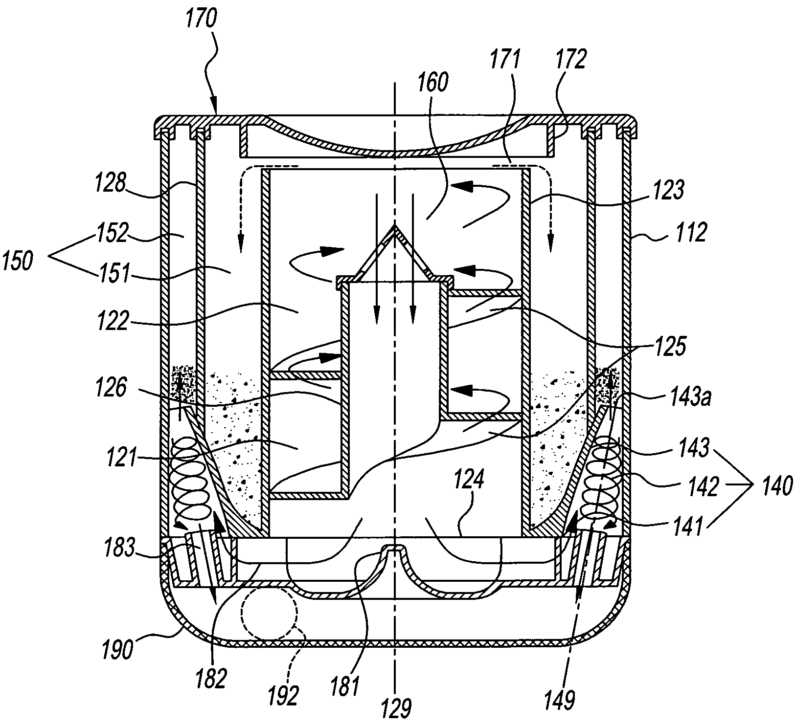
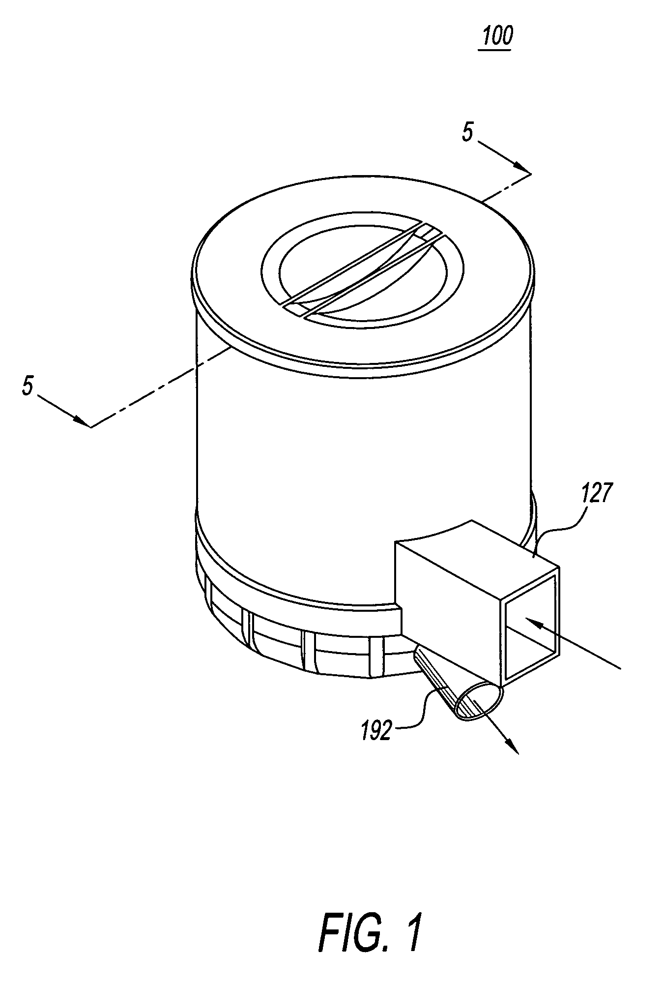
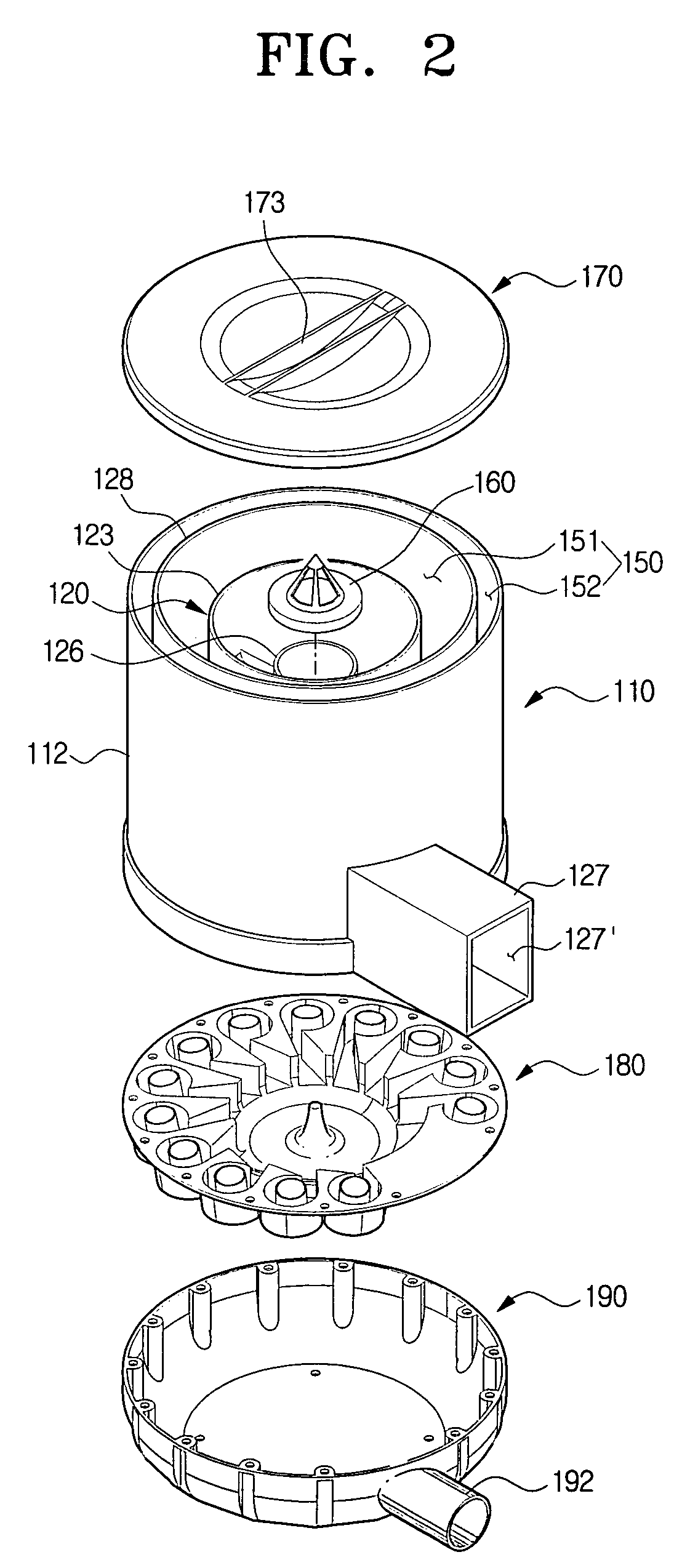
[0029]Referring to FIGS. 1 through 6, a multi-cyclone dust collection apparatus 100 comprises a first cyclone having a first cyclone body 120, an air inflow port 127 defining an inlet 127′, and an air outlet 124, and second cyclones respectively having an air inlet 141, a second cyclone body 130 and discharge guide flow paths 182 which serve as outlets. Since each of the second cyclones is formed in a cone shape, they will be hereinafter referred to as a “second cyclone”.

[0030]As shown in the drawings, the inlet 127′ is formed at the lower part of the first cyclone and the discharge guide flow paths 182 serving as outlets, are formed at the lower part...


PUM

PropertyMeasurementUnit
centrifugal forceaaaaaaaaaa
forceaaaaaaaaaa
heightaaaaaaaaaa

Abstract

A multi-cyclone dust collection apparatus is disclosed that comprises a first cyclone having an air inlet, in which the air introduced into the first cyclone through the air inlet is caused to swirl and ascend in the first cyclone so that dust is separated from the air; and a plurality of second cyclones arranged around the lower part of the first cyclone, in which the air discharged from the first cyclone into the second cyclones is further caused to swirl and ascend so that dust is separated from the air. Each of the second cyclones is provided with an air outlet through which the purified air is discharged. The air inflow port is provided at the bottom of the first cyclone and the outflow ports are provided at the lower ends of the second cyclones.

Description

CROSS-REFERENCE TO RELATED APPLICATIONS[0001]This application claims the benefit of Korean Patent Application No. 2005-95102 filed on Oct. 10, 2005 with the Korean Intellectual Property Office, the disclosure of which is incorporated herein by reference.BACKGROUND OF THE INVENTION[0002]1. Field of the Invention[0003]The present invention relates to a vacuum cleaner, and in particular, to a multi-cyclone dust collection apparatus, which is employed in a vacuum cleaner so as to filter dirt suctioned from a surface to be cleaned together with air, using centrifugal force over two or more steps.[0004]2. Description of the Related Art[0005]In general, a cyclone vacuum cleaner comprises a bottom brush for suctioning dirt from a surface to be cleaned together with air, a motor driving chamber provided with a driving source, and a vacuum cleaner body provided with a cyclone collection apparatus.[0006]The cyclone collection apparatus is constructed in such a way that dust-entrained air, whic...

Claims


Application Information

Patent Timeline
Patent Type & Authority Patents(United States)
IPC IPC(8): B01D45/12
CPCA47L9/1608A47L9/1625A47L9/1641A47L9/1658A47L9/1683B04C5/12B04C5/26Y10S55/03A47L9/16A47L9/10
Inventor OH, JANG-KEUN
Owner SAMSUNG GWANGJU ELECTRONICS CO LTD
Why Eureka
Try Eureka