
Compressor

A compressor and compression mechanism technology, applied in the field of compressors, can solve problems such as temperature rise, and achieve the effects of preventing ozone layer destruction, suppressing temperature rise, and preventing global warming

Active Publication Date: 2015-07-22
PANASONIC INTELLECTUAL PROPERTY MANAGEMENT CO LTD
View PDF8 Cites 0 Cited by
  • Summary
  • Abstract
  • Description
  • Claims
  • Application Information

AI Technical Summary

Problems solved by technology

[0003] However, the above-mentioned refrigerant has the property of being easily decomposed at high temperature, so it is necessary to suppress the temperature rise

Method used


Image

  • Compressor
  • Compressor
  • Compressor

Examples


Embodiment approach 1

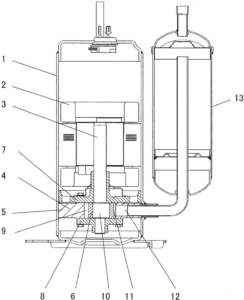
[0036] figure 1 It is a longitudinal sectional view of the overfeed (boost) type compressor in Embodiment 1 of the present invention.

[0037] exist figure 1 In the airtight container 1, an electric component 2 is accommodated. The compression mechanism unit 4 is driven by the drive shaft 3 in the vertical direction of the electric component 2 . The compression mechanism unit 4 is configured such that an upper bearing 7 and a lower bearing 8 sandwich a cylinder 5 , a rotary piston 6 , and vanes to form a compression chamber 9 and perform a compression operation. A crankshaft eccentric portion 10 integrally formed with the drive shaft 3 is accommodated in the cylinder 5 , and the rotary piston 6 is rotatably attached to the crankshaft eccentric portion 10 . In the cylinder 5 , vanes (not shown) are provided in contact with the rotary piston 6 , and are divided into a compression chamber 9 and a suction chamber 11 . A suction port 12 communicating with the suction chamber ...

Embodiment approach 2

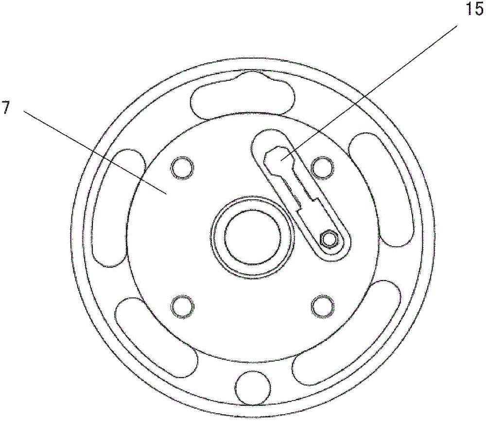
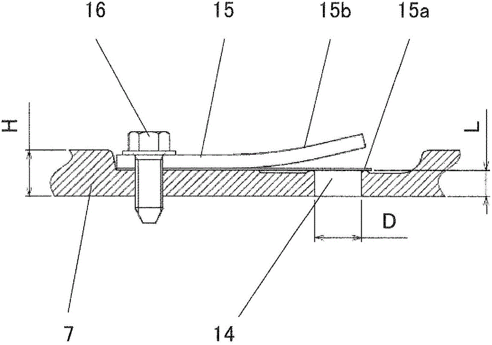
[0069] Figure 7 is a front view of the lower bearing 8 provided with the discharge check valve 15, Figure 8 It is a cross-sectional view of the lower bearing 8 taken along the longitudinal direction of the discharge check valve 15 . The discharge check valve 15 includes: a tongue valve 15 a for opening and closing the discharge port 14 ; and a tongue valve 15 b for restricting lift when the valve valve 15 a is opened.

[0070] In Embodiment 2, compared to Embodiment 1, the discharge check valve 15 is configured to move to the lower bearing 8 , and the same effects as those in Embodiment 1 can be obtained.

[0071] In addition, the lower bearing 8 is immersed in the lubricating oil accumulated in the lower part of the airtight container 1, so the noise generated by the discharge check valve 15 is attenuated by the lubricating oil, and it is difficult to transmit to the outside of the compressor, so a low-noise compressor can be provided. .


PUM


Abstract

A single-component refrigerant mainly comprising hydrofluoroolefin having a carbon-carbon double bond or a mixture refrigerant including this refrigerant is used as a refrigerant. An axial length L of a discharge port 14 is set to be less than a thickness H of a member in which the discharge port 14 is formed, thereby making it possible to reduce a length of the discharge port in a direction of a flow passage to reduce a pressure loss and restrain an unnecessary pressure increase in a compression mechanism 4 to reduce a temperature increase of the refrigerant. At the same time, because a volume of the discharge port 14 filled with a high-pressure gas refrigerant can be made smaller, the high-pressure gas refrigerant remaining in the discharge port 14 after completion of a discharge process in the compression mechanism 4 is restrained from flowing back toward a low-pressure side compression chamber 9. Accordingly, a temperature increase of the refrigerant caused by re-expansion and re-compression can be also restrained.

Description

technical field [0001] The present invention relates to indoor air conditioners, refrigerators, Compressors in the refrigeration cycle of other air conditioning devices, heat pump water heaters, etc. Background technique [0002] In existing refrigerating devices, HFCs (hydrofluorocarbons) with an ozone depletion coefficient of 0 are being used as working refrigerants. become a problem. Therefore, Patent Document 1 discloses a refrigerant mainly composed of a hydrofluoroolefin having a carbon-to-carbon double bond that does not contain chlorine atoms and has a low global warming coefficient. [0003] However, the above-mentioned refrigerant has the property of being easily decomposed at high temperature, so it is necessary to suppress the temperature rise. [0004] The following three factors are mainly cited as factors for the temperature rise of the refrigerant in the compression mechanism unit. The first is the temperature rise caused by adiabatic compression, which i...

Claims


Application Information

Patent Timeline
Patent Type & Authority Patents(China)
IPC IPC(8): F04C29/12F04B39/10F04C18/356
CPCF04C29/12F04C2250/102F04B39/1066F04C2210/263F04C18/3564F04B39/1073F04B39/0055F04C23/008
Inventor 吉田裕文饭田登大八木信吾中井启晶苅野健大野龙一
Owner PANASONIC INTELLECTUAL PROPERTY MANAGEMENT CO LTD
Learn More