Concentric co-extrusion die for extruding a multilayer thermoplastic film

a thermoplastic film and coextrusion die technology, applied in the field of concentration coextrusion die for extruding multi-layer thermoplastic film, can solve the problems of increased melt temperature and material degradation, complex internal construction of dies, and the size of dies that cannot reduce the thickness of specific layers, so as to improve the thickness tolerance

Active Publication Date: 2018-01-16
PLASTIKA KRITIS
View PDF51 Cites 0 Cited by
  • Summary
  • Abstract
  • Description
  • Claims
  • Application Information

AI Technical Summary

Benefits of technology

[0032]It has been found that this significantly shortens the flow path length between the layer inlet and the start of the helical outlet channel compared to the corresponding flow path length for the same layer of the same size in a conventionally centrally fed concentric mandrel die as well significantly shortens residence time in the die. In addition pressure drop is minimised between the layer inlet and the start of the helical outlet channels compared to the pressure drop across the corresponding section of the same layer of a same size centrally fed concentric mandrel die. The reduction in pressure allows the gain in pressure to be used or partially used in the helical section of the layer to improve thickness uniformity. This results in better controlling of the uniformity of thickness of this layer by optimising the distribution of the melt flow around the circumference of the die.
[0033]In addition, although the presence of multiple side entry inlets may complicate the construction of the die as the side inlets have to pass through multiple other layers of the die, avoiding interference with channels in the other layers, and hence is counter-intuitive, due to the peripheral feed of the material and the shorter flow paths the melt is distributed around the circumference in an optimal way resulting in uniform thickness distribution even at very low percentages and outputs of the respective layer(s).
[0039]Another possibility is to improve the thickness tolerance by controlling separately the throughput of each extruder supplying said mandrel, and in this way to correct thickness deviations around the bubble circumference. This can be done with or without melt pumps and can be connected with a thickness measurement unit for on-line thickness control.

Problems solved by technology

As can be seen, such dies have complex internal constructions, requiring the accurate registration of components in the different layers.
As a consequence, higher melt pressures are developed in use and the material residence time gets longer, resulting in increased melt temperatures and material degradation.
In addition the size of the die does not allow reducing the thickness of a specific layer while maintaining good thickness uniformity of this layer due to the very long paths that the melt has to flow though within the die and the required low material quantity for such layer.
Further, the back pressure developed between the layer inlet and the start of the helical outlet becomes very high, reducing the remaining available pressure which can be used for the helical outlet section of the layer to improve thickness uniformity due to the fact that total available pressure is limited.
Residence time and melt distribution around the die circumference is also a very critical issue for large dies, especially for sensitive materials because of carbon build up, high purging time, waste, deposits, etc.
(slow moving particles are prone to degradation and long purging time).
Such materials need to be processed with a very short residence time and also need to be used in very low percentages due to their significantly higher cost in relation to standard materials.

Method used


Image

  • Concentric co-extrusion die for extruding a multilayer thermoplastic film
  • Concentric co-extrusion die for extruding a multilayer thermoplastic film
  • Concentric co-extrusion die for extruding a multilayer thermoplastic film

Examples


Embodiment Construction

IN ACCORDANCE WITH THE INVENTION

[0054]In the examples described below, the mandrel exit diameter is shown to be 1800 mm. However co-extrusion dies according to the present invention can have any desired exit diameter, but are especially suitable for diameters in the range of 1300 to 2500 mm. The detailed design of all parts depends on the final application as well as required residence time, pressure and other rheological parameters.

[0055]In the detailed description that follows, all the data of the dies mentioned (dimensions, number of extruders, total number of layers, number of layers which are side fed with multiple inlets, number of inlets per layer, number of bifurcations, number of spirals overlaps, number of spirals, number of radial ports, inclination of ports, inclination of side feed inlets etc) are indicative and only for the purpose of the examples.

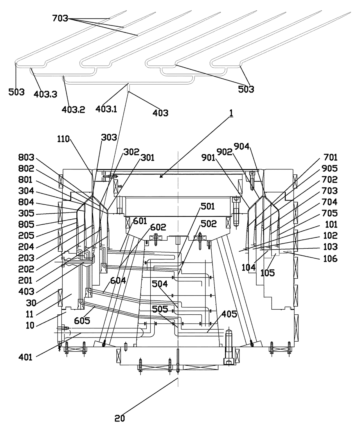
[0056]In FIG. 4, a longitudinal section of a first concentric co-extrusion die is shown as well as a developed partial annu...


PUM

PropertyMeasurementUnit
diameteraaaaaaaaaa
lengthaaaaaaaaaa
lengthaaaaaaaaaa

Abstract

A large concentric co-extrusion die (1) is described having a plurality of annular or conical die mandrel layers (201-205). Each layer is formed between a pair of adjacent annular or conical die mandrels (101-106) defining between them a flow path for molten thermoplastics material from an inlet to an annular extrusion outlet (110) through which a thermoplastics tubular extrusion is formed in use. Extrusion takes place through the multiple annular layer outlets (301-305) to form a multi-layered product. At least one layer (203) of the annular or conical die mandrels has a plurality of molten material inlets arranged around the external circumference of the co-extrusion die with each inlet being connected to a feed channel (403) which has plural bifurcations (403.1, 403.2, 403.3) providing 2n subsidiary outlet feed channels (503) where n is the number of bifurcations. Each subsidiary outlet feed channel being connected to a corresponding helical outlet channel (703).

Description

CROSS-REFERENCE TO RELATED APPLICATIONS[0001]The present application is a national phase entry under 35 U.S.C. §371 of International Application No. PCT / EP2012 / 0064140, filed Jul. 19, 2012 and published on Jan. 24, 2013 as WO 2013 / 011079, which claims priority from United Kingdom Patent Application No. 1112475.7, filed Jul. 20, 2011, the disclosures of which are incorporated herein by reference in their entirety.[0002]The present invention relates to extrusion dies and, more particularly, to co-extrusion dies and especially those for extruding large width blown films using thermoplastic materials.BACKGROUND[0003]The basic function of any blown film extrusion die is to take one or more melt streams entering the die and distribute them to a single concentric annular melt stream at the die exit as uniformly as possible.[0004]A number of different types of extruder die are known in the art. Concentric helical mandrel dies are cylindrical in shape and are mounted one above another secure...

Claims


Application Information

Patent Timeline
Patent Type & Authority Patents(United States)
IPC IPC(8): B29C47/26B29C47/06B29C47/56B29C47/36B29C47/70B29C47/00B29C48/10B29C48/21B29C48/335B29C48/495
CPCB29C47/268B29C47/0026B29C47/065B29C47/261B29C47/705B29C47/265B29C47/364B29C47/56B29C47/70B29C47/263B29C48/10B29C48/3366B29C48/30B29C48/49B29C48/21B29C48/338B29C48/695B29C48/3363B29C48/37B29C48/336B29C48/705B29C48/495B29C48/18B29C48/335
Inventor LEMPIDAKIS, EMMANOUILMELAS, IOANNISKALARAKIS, MINAS
Owner PLASTIKA KRITIS
Why Eureka
Try Eureka