Melt distributor

a technology of distributors and melts, applied in the field of melt distributors, can solve the problems of inability to use articles manufactured during color change, risk of melting thermal degradation,

Pending Publication Date: 2022-09-15
KRUPP KAUTEX MASCHINENBAU GMBH
View PDF0 Cites 0 Cited by
  • Summary
  • Abstract
  • Description
  • Claims
  • Application Information

AI Technical Summary

Problems solved by technology

This deflection by 90° produces dead zones in the melt flow, in which there is a risk of a thermal degradation of the melt.
The a

Method used


Image

  • Melt distributor
  • Melt distributor
  • Melt distributor

Examples


Embodiment Construction

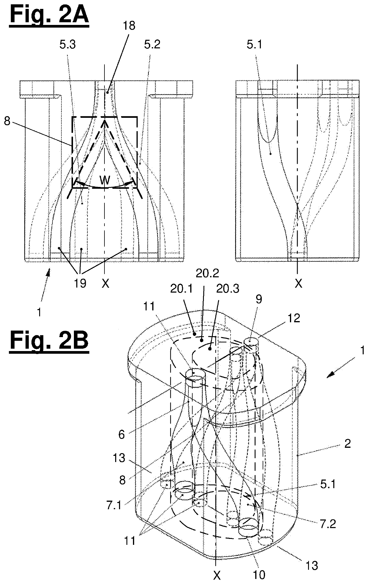
[0041]Referring to the drawings, A preferred embodiment of the melt distributor 1 according to the present disclosure is shown in related views in FIGS. 2A and 2B.

[0042]The melt distributor 1 comprises in the example a one-piece, metallic component 2 with an inlet side 3 and with an outlet side 4. The inlet side 3 is the upper side in the example and the outlet side 4 is the opposing lower side. This constellation is assumed below for simplification of the view. As an alternative, the inlet side 3 and the outlet side 4 may have a different orientation in relation to one another or in space.

[0043]Three bifurcated melt passages 5.1, 5.2, 5.3 extend between the inlet side 3 and the outlet side 4 in the example shown. The number of the melt passages may deviate from this example. One, two, three, four or even more melt passages may be provided. These melt passages may preferably be located in space zones adjacent to one another, so that the melt passages do not touch each other. One or ...


PUM

PropertyMeasurementUnit
Angleaaaaaaaaaa
Lengthaaaaaaaaaa
Flow rateaaaaaaaaaa

Abstract

A melt distributor (1) having a plurality of bifurcated melt passages melt passages (5.1, 5.2, 5.3) for redirecting and distributing melt flows from a thermoplastic plastic. The melt distributor can be connected to a multiple extrusion head for producing multi-layer preforms. The branched junction (8) is configured as a rounded y-shaped conduit branch, and at least the branched junction (8) between a supply passage part (6) and the discharging passage parts (7.1, 7.2) of the bifurcated melt passage follows a continuously bent curve, the curvature of which is not equal to zero. The rounded and continuously bent configuration of the branched junction (8) contributes to shorter flow paths and avoids the formation of dead zones.

Description

CROSS REFERENCE TO RELATED APPLICATIONS[0001]This application is a United States National Phase Application of International Application, PCT / EP2020 / 071680, filed Jul. 31, 2020, and claims the benefit of priority under 35 U.S.C. § 119 of German Applications 10 2019 121 172.7, filed Aug. 6, 2019 and 10 2019 127 661.6, filed Oct. 15, 2019, the entire contents of which are incorporated herein by reference.TECHNICAL FIELD[0002]The present invention pertains to a melt distributor, and especially to a melt distributor with a plurality of bifurcated (melt) line passages for deflecting and distributing melts from thermoplastic plastic, The melt distributor can be connected indirectly or directly to a multilayer extrusion head for the manufacture of multilayer preforms from the melt.TECHNICAL BACKGROUND[0003]DE 2100192 A discloses that two tubular partial flows essentially extending coaxially to one another, the seam areas of which extending in the longitudinal direction are arranged offset ...

Claims


Application Information

Patent Timeline
IPC IPC(8): B29C48/71B29C48/345B29C48/495B29C48/335B29C48/21
CPCB29C48/71B29C48/345B29C48/495B29C48/335B29C48/21B29C49/04B29C48/705B29C48/09B29C48/0255B29C48/0017B29C48/362B29C49/22
Inventor MIELKE, MAURICEMÜLLER, MICHAELHOLZKY, WERNER
Owner KRUPP KAUTEX MASCHINENBAU GMBH
Why Eureka
Try Eureka