Extruder

A technology of extrusion machine and extrusion wheel, which is applied in the direction of metal extrusion dies, etc., can solve the problems of long billet flow channel, huge equipment, low yield, etc., to avoid sags and cracks, improve product quality, and have sufficient billets Effect

Active Publication Date: 2012-05-30
HEFEI SMARTER TECH GROUP CORP
View PDF0 Cites 1 Cited by
  • Summary
  • Abstract
  • Description
  • Claims
  • Application Information

AI Technical Summary

Problems solved by technology

[0002] At present, due to the large diameter of the metal outer sheath of the ultra-high voltage cable, it is generally formed by welding a metal strip, that is, seam welding. The material grains at the welding place of this welding method are coarse and uneven, which affects the electrical and electrical properties of the cable. mechanical physical properties
The continuous aluminum pressing machine produced with aluminum ingots has huge equipment, high energy consumption, complex structure and high cost. However, the traditional continuous extrusion machine has a structure of single wheel and single groove or single wheel and double groove. This structure is relatively simple. Since this kind of equipment has only one runner, the extrusion chamber has only one hole communicating with it, so the flow path of the billet in the extrusion chamber is long, resulting in a large temperature difference between the upper and lower sides, and the product qualification rate is low. This single wheel single groove or single wheel The double-slot structure can usually only produce products with small diameters and small cross-sections. It is very difficult to produce products with large diameters, and the yield is low.

Method used


Image

  • Extruder
  • Extruder
  • Extruder

Examples


Embodiment Construction

[0018] The present invention will be further described below in conjunction with accompanying drawing:

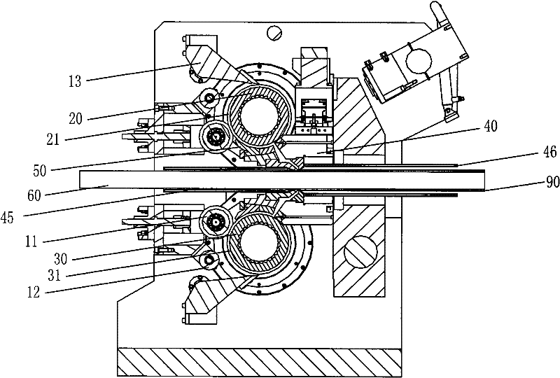
[0019] Extrusion machine comprises frame 10, and frame 10 is archway shape, and the extruding wheel 20,30 that two rotating shafts are parallel to each other is set on frame 10, as the preferred scheme of the present invention, selects extruding wheel 20,30 to be arranged as The structure arranged in parallel above and below is also described in the following description as the structure arranged in parallel above and below.

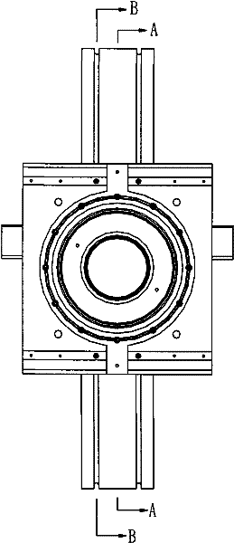
[0020] Such as figure 1 , Figure 5 As shown, the rotating shafts 22, 32 of the extrusion wheels 20, 30 are arranged in parallel up and down, the direction of rotation of the extrusion wheels 20, 30 is opposite, and the rims are respectively provided with at least one extrusion wheel groove 21, 31 in the circumferential direction, The extrusion wheel grooves 21, 31 are respectively provided with a guide seat 50 matched therewith, and the guide seat ...


PUM


Abstract

The invention relates to an extruder. Extruding wheels with rotary shafts which are parallel to each other are arranged on a rack of the extruder, the rotation directions of the extruding wheels are reverse, at least one extruding wheel slot at the circumferential direction is respectively arranged on wheel rings, a guide seat which is matched with the extruding wheel slot is respectively arranged on the extruding wheel slot, the guide seat and the extruding wheel slot form an extruding cavity which is passed by a billet, a mold base is arranged between the extruding wheels, a channel passed by a cable is arranged in the mold base, holes which are communicated with the extruding cavity are symmetrically arranged on two sides of a shaft core line of the mold base along radial direction, the holes are communicated with a coating cavity of the mold base, and an outlet of the coating cavity is coated on the periphery at the outlet end of the cable in the channel. The extruding billet enters the extruding cavity and then enters the coating cavity through the holes on the mold base, as the holes are symmetrically arranged along the radial direction of the mold base, the extruding billetsimultaneously enters the coating cavity at the upper and the lower positions of the mold base, a flow passage of the billet is shortened, the temperature difference is small, the billet which passesthe mold base is enough, and the yield is improved.

Description

technical field [0001] The present invention relates to an extrusion machine, in particular to an extrusion equipment for forming metal by continuous extrusion. Background technique [0002] At present, due to the large diameter of the metal outer sheath of the ultra-high voltage cable, it is generally formed by welding a metal strip, that is, seam welding. The material grains at the welding place of this welding method are coarse and uneven, which affects the electrical and electrical properties of the cable. mechanical physical properties. The continuous aluminum pressing machine produced with aluminum ingots has huge equipment, high energy consumption, complex structure and high cost. However, the traditional continuous extrusion machine has a structure of single wheel and single groove or single wheel and double groove. This structure is relatively simple. Since this kind of equipment has only one runner, the extrusion chamber has only one hole communicating with it, so...

Claims


Application Information

Patent Timeline
Patent Type & Authority Patents(China)
IPC IPC(8): B21C23/21B21C25/02
CPCB21C23/30B21C25/02
Inventor 岳光明陈学模向晓红
Owner HEFEI SMARTER TECH GROUP CORP
Why Eureka
Try Eureka