Hydraulic circuit arrangement for operating a hydrodynamic torque converter

a technology of hydrodynamic torque converter and hydrodynamic circuit, which is applied in the direction of rotary clutches, fluid couplings, gearings, etc., can solve the problems of pressure loss and reduce the oil flow through the converter, and achieve the effect of less loss and less pressure loss

Active Publication Date: 2009-12-03
ZF FRIEDRICHSHAFEN AG
View PDF23 Cites 2 Cited by
  • Summary
  • Abstract
  • Description
  • Claims
  • Application Information

AI Technical Summary

Benefits of technology

[0004]The purpose of the present invention is to reduce pressure losses during operation of the converter and the converter clutch.
[0005]According to the invention it is provided that a line through which the oil flows back when the converter clutch is disengaged, is made as a bypass line around the hydraulic switching unit and is connected directly to the oil cooler. Bypassing of the hydraulic switching unit gives the advantage that the pressure drop of the oil flowing back from the converter clutch and into the cooler is reduced.
[0007]In an advantageous further development a 2 / 2-way valve is arranged in the bypass line, which is controlled by the disengaging pressure of the converter clutch. This gives the advantage that when the disengaging pressure for the converter clutch is applied on the 2 / 2-way valve the bypass line is opened and the direct flow path to the oil cooler is available. Thus, the return flow of oil takes place with lower pressure losses than in the prior art.
[0008]An advantageous embodiment provides that the bypass line with the valve is connected between the first line and a third line which connects the hydraulic switching unit to the cooler. This provides a shorter flow path with relatively less loss from the converter to the oil cooler.

Problems solved by technology

The disadvantage of this known oil flow system is that the return flow of the oil when the converter clutch is disengaged takes place via the hydraulic switching unit or the corresponding control valve, and this causes a pressure loss which reduces the oil flow through the converter.

Method used


Image

  • Hydraulic circuit arrangement for operating a hydrodynamic torque converter
  • Hydraulic circuit arrangement for operating a hydrodynamic torque converter
  • Hydraulic circuit arrangement for operating a hydrodynamic torque converter

Examples


Embodiment Construction

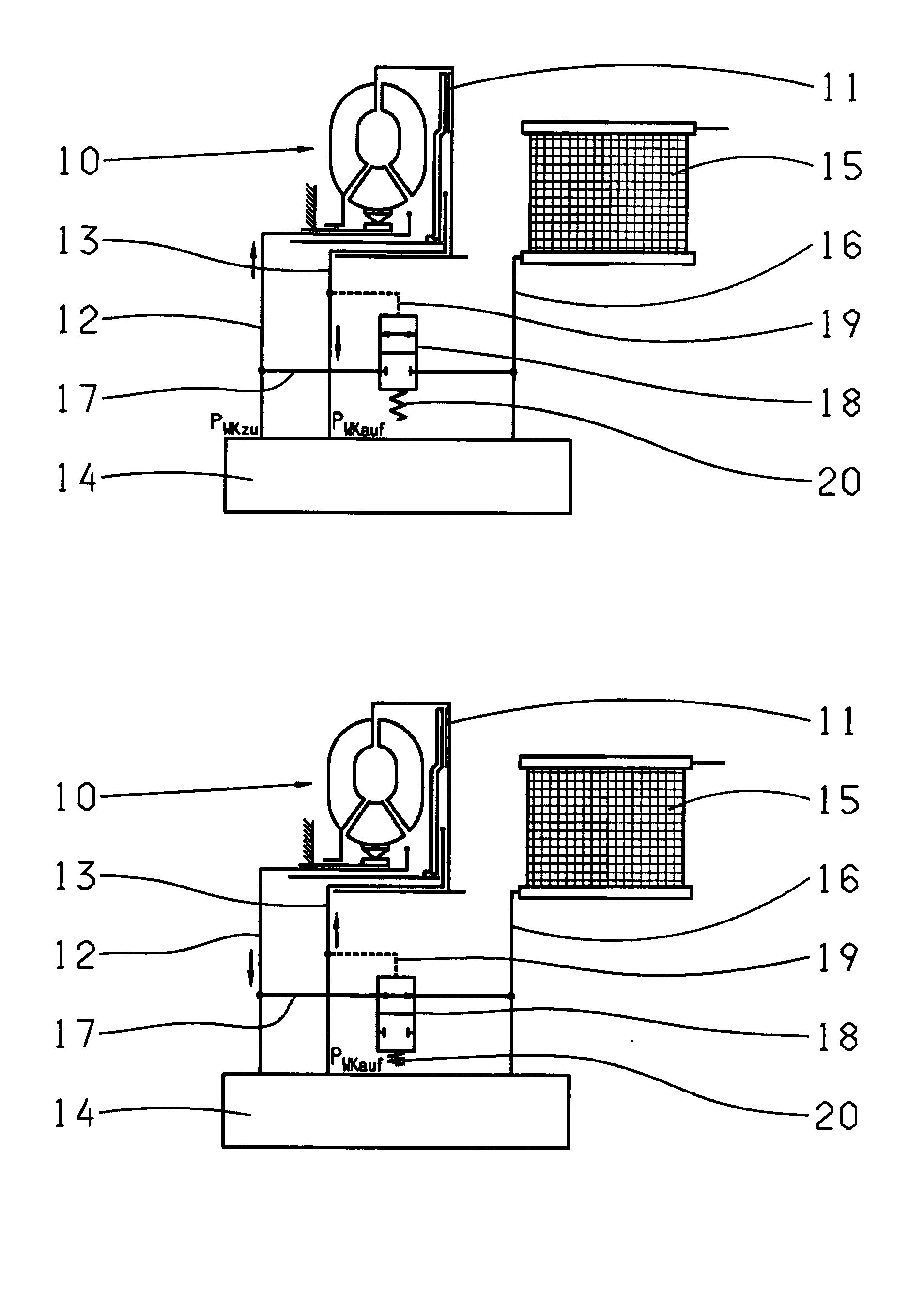
[0014]FIG. 1 shows a hydraulic circuit arrangement for a hydrodynamic torque converter 1, called the converter 1 in what follows, which is connected to an automatic change-speed transmission 2. The converter 1 and transmission 2 form an automatic transmission known for driving motor vehicles. The hydraulic circuit arrangement also comprises a hydraulic switching unit 3 which, from an oil source (not shown), for example an oil pump driven by the converter 1, is supplied with pressure oil as indicated by an arrow F. In addition the hydraulic circuit arrangement comprises an oil cooler 4 which, in the form of an air-cooled or water-cooled heat exchanger, serves to cool the circulated oil. The converter 1, which comprises a converter bridging clutch (not shown) called the converter clutch in what follows, is connected by two hydraulic lines 5, 6 to the hydraulic switching unit 3. The transmission 2 is connected to the hydraulic switching unit 3 by a further line 7, a lubrication oil lin...


PUM


Abstract

A hydraulic circuit arrangement for operating a hydrodynamic torque converter (1, 10) with a converter bridging clutch (11). The circuit arrangement comprises a hydraulic switching unit (3, 14) having at least one valve for controlling an inflow flow and a return flow of oil to the converter (1, 10) and the converter bridging clutch (11), an oil cooler (4, 15), a first line (5, 12) for acting upon the converter bridging clutch (11) with an engagement pressure (PWKzu) and a second line (6, 13) for acting upon the converter bridging clutch (11) with a disengagement pressure (PWKauf). The circuit arrangement comprises a bypass line (8, 17) which is connected directly with the oil cooler (4, 15) so as to bypass the hydraulic switching unit (3, 14).

Description

[0001]This application claims priority from German patent application serial no. 10 2008 002 141.5 filed Jun. 2, 2008.FIELD OF THE INVENTION[0002]The invention concerns a hydraulic circuit arrangement and a method for the control of a converter bridging clutch.BACKGROUND OF THE INVENTION[0003]Hydrodynamic torque converters, also called converters for short in what follows, are used as starting aids in automatic transmissions for motor vehicles. To improve the efficiency of the automatic transmission the converter is equipped with a converter bridging clutch, called a converter clutch for short in what follows. Known converter clutches comprise a clutch piston, which is acted upon by a hydraulic liquid, referred to as oil in what follows, and thereby forms a torque connection between a pump wheel and a turbine wheel. The converter is thus bridged. The oil is supplied to the converter or converter clutch by two lines coming from a hydraulic switching unit which, as a rule, is arranged...

Claims


Application Information

Patent Timeline
Patent Type & Authority Applications(United States)
IPC IPC(8): F16H61/14
CPCF16H41/30Y10T477/73F16H61/143F16H61/0206
Inventor LEICHSENRING, HORSTHAIRSTON, BERRONBIRKLE, JOCHENAISENPREIS, THOMAS
Owner ZF FRIEDRICHSHAFEN AG
Why Eureka
Try Eureka