Escape device

a technology of a braking system and an escape device, which is applied in the direction of cleaning equipment, sports equipment, applications, etc., can solve the problems of affecting the safety of people on the upper floors, the inability to use elevators, and the difficulty of evacuating from multi-story buildings, etc., and achieves a more responsive braking system and substantial braking

Inactive Publication Date: 2010-03-30
LEE TERRY VICTOR
View PDF10 Cites 3 Cited by
  • Summary
  • Abstract
  • Description
  • Claims
  • Application Information

AI Technical Summary

Benefits of technology

[0012]By producing a braking effect responsive to the speed of the device it is possible to have a regulated a smoother descent.
[0016]Conveniently, the device includes a back plate mounted thereto said back plate adapted to be strapped to a back of a person to thereby secure said person to said device. A simple harness makes the device easy to carry and deploy.
[0019]The braking mechanism may be operatively connected to said cable dispensing assembly through a geared arrangement. The use of a geared arrangement allows the device to have a more responsive braking system.
[0023]Preferably, the cable is adapted to be connected at a free end thereof to a launch arm attached to a building. A launch arm may consist of a channel member having a track therein adapted to hold a runner attached to a free end of the cable. By attaching the device to a building in this way the user is able to position themselves clear on any obstructions on the descent.

Problems solved by technology

In emergencies evacuation from multi-story buildings is problematic.
Specifically, where a situation, for example, a fire occurs in a lower floor people on upper floors may be trapped.
In such situations use of elevators is generally not recommended and, where interruptions to power supply occur, is not possible.
However, public confidence in the ability of fire proofing systems is not high.
Further, it has become apparent that there are emergency situations that may arise as a result of deliberate sabotage in which the structural integrity of the building is compromised.
In such situations fast escape from the building may be required for large numbers of personnel in a short space of time to avoid injury and fatality on a large scale as a building collapses.
This approach is not suitable for use in very high buildings, nor is the approach suitable for the escape of the large numbers of people that may need to leave a building at any one time.
However, these devices frequently operate on the basis of a friction brake with a simple on / off mechanism that causes jarring in use and, as such they are not suitable for traversing the distances needed to be travelled to reach ground level safely from many modern buildings.
For example, the construction of the devices may be such that they would conceivably be very bulky if constructed for use in higher buildings, or the heat generated during their use would make them impractical.
For this reason existing portable escape and descent devices are perhaps providing illusory reassurance to their owners.

Method used


Image

  • Escape device
  • Escape device
  • Escape device

Examples


Embodiment Construction

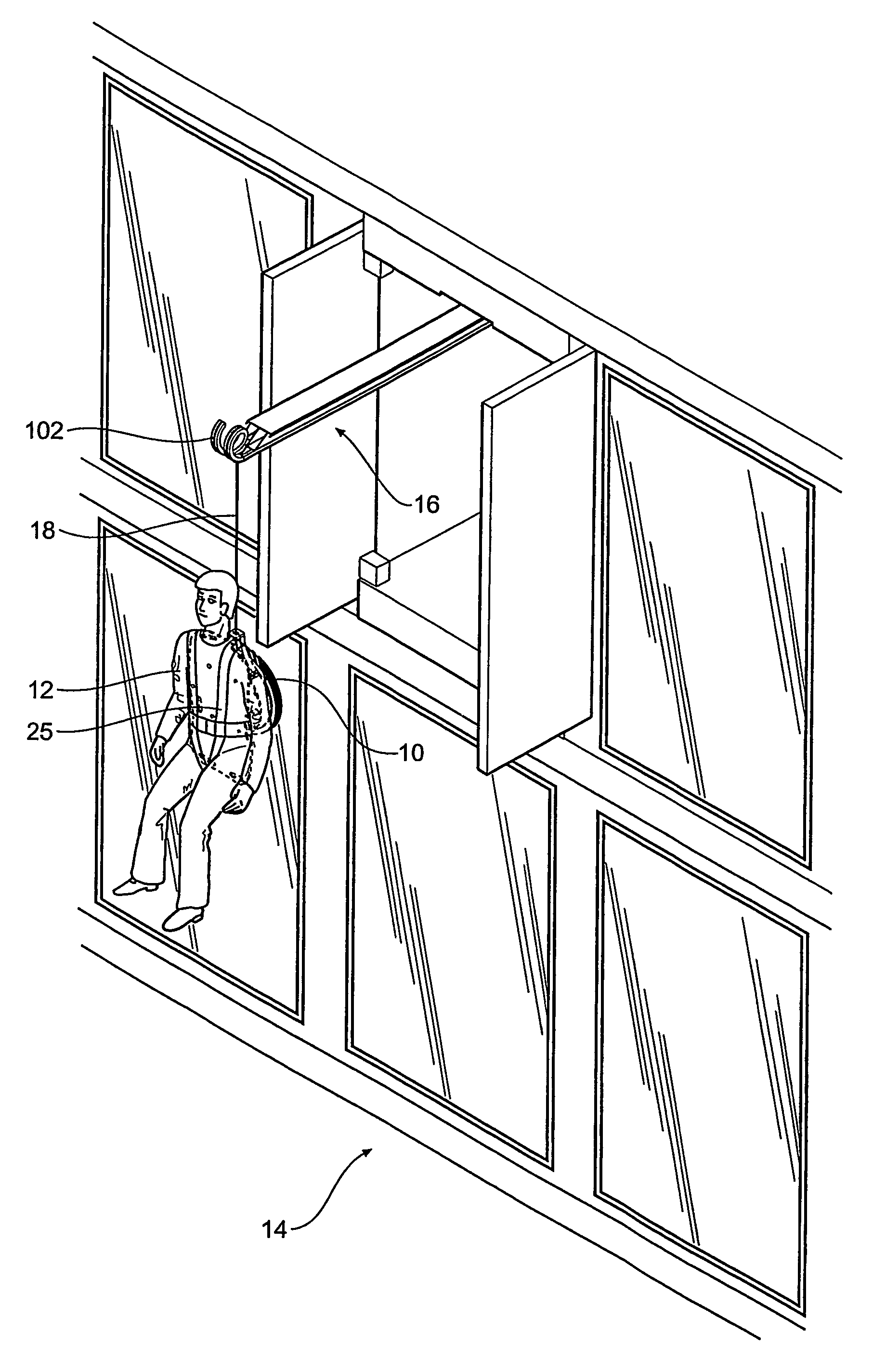
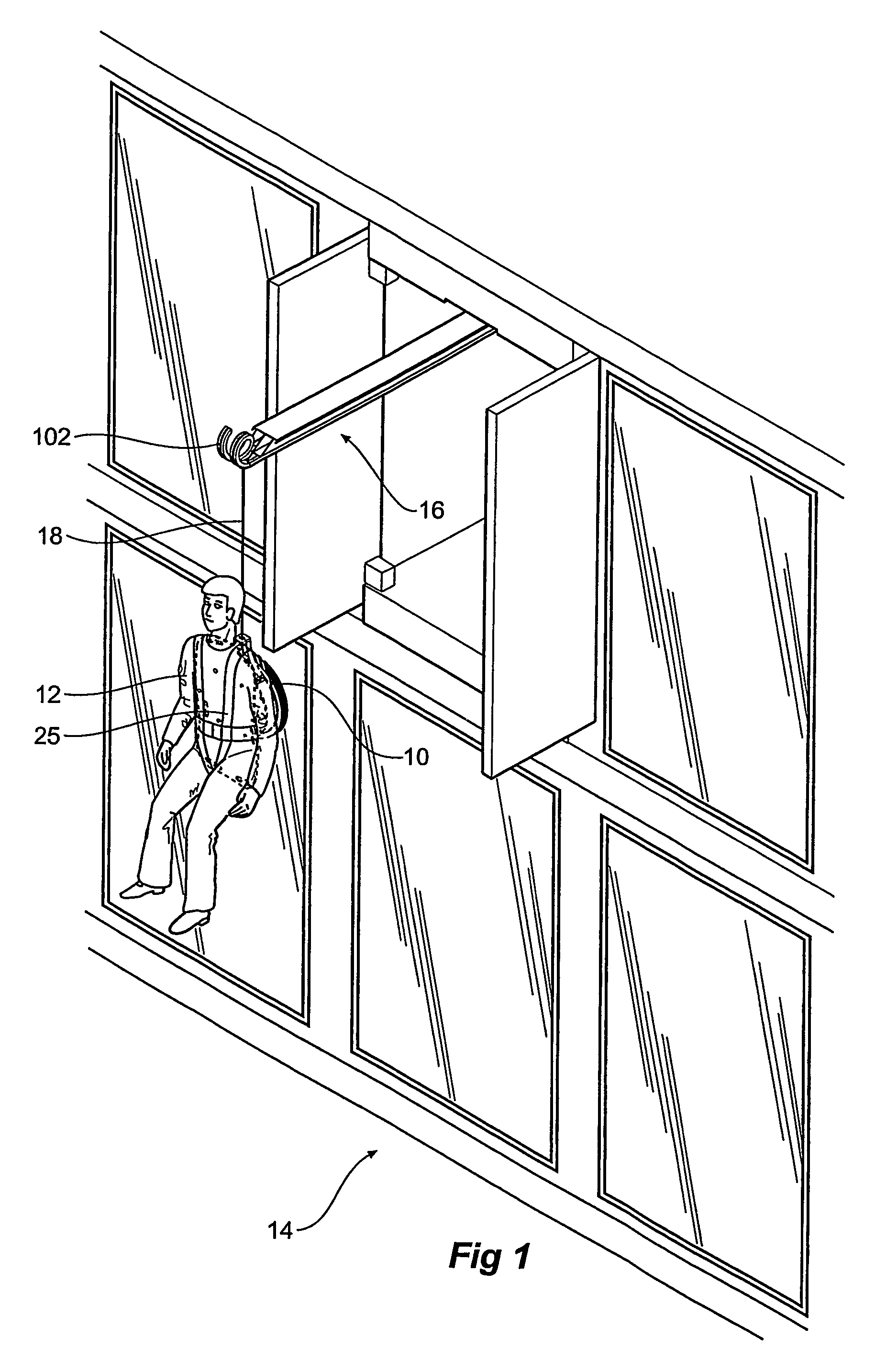
[0050]The drawings illustrate the various components of an escape device 10 constructed in accordance with the present invention. The device 10 is designed for rapid deployment and may be used to evacuate large numbers of personnel 12 from modern multi-story buildings 14 in a short space of time. The device 10 is designed to be used in conjunction with a launch arm building attachment 16, which can be seen more clearly in FIGS. 21 to 23. In use it is anticipated that a unit 10 may be individually owned and carried from building to building as required by the owner 12, or, alternatively that a number of units 10 may be held in any one building for use by the occupants as and when the need arises.

[0051]FIG. 1 illustrates the escape device 10 in use by a person 12 descending from an elevated level of a building 14. The person 12 is suspended from an attachment 16 to which the unit is connected via a cable 18 so that he or she may descend the outside of the building 14 until safely on t...


PUM


Abstract

An escape device (10) including a cable (18), a rotatable cable dispensing assembly (22) from which the cable (18) is dispensed under load, a braking mechanism (28) operatively connected to the rotatable cable dispensing assembly (22), whereby a braking response of the braking mechanism (18) is proportional to the rate at which cable (18) is dispensed from the rotatable cable dispensing assembly (22).

Description

FIELD OF THE INVENTION[0001]The present invention relates to an escape device. The device of the present invention is directed to a device that enables escape from high-rise buildings.BACKGROUND OF THE INVENTION[0002]In emergencies evacuation from multi-story buildings is problematic. Specifically, where a situation, for example, a fire occurs in a lower floor people on upper floors may be trapped. In such situations use of elevators is generally not recommended and, where interruptions to power supply occur, is not possible. Many modern buildings are constructed so as to include fireproof floors at some levels. However, public confidence in the ability of fire proofing systems is not high. Further, it has become apparent that there are emergency situations that may arise as a result of deliberate sabotage in which the structural integrity of the building is compromised. In such situations fast escape from the building may be required for large numbers of personnel in a short space ...

Claims


Application Information

Patent Timeline
Patent Type & Authority Patents(United States)
IPC IPC(8): A62B1/10
CPCA62B1/10
Inventor LEE, TERRY VICTOR
Owner LEE TERRY VICTOR
Why Eureka
Try Eureka