Energy-saving, efficient and low-noise press hydraulic system
What is Al technical title?
Al technical title is built by PatSnap Al team. It summarizes the technical point description of the patent document.
A technology of hydraulic system and low noise, applied in the field of hydraulic system of presses, can solve the problems of low system efficiency, high noise and high cost, and achieve the effects of high system efficiency, low noise and low power consumption
Active Publication Date: 2021-08-27
TIANJIN SINO GERMAN VOCATIONAL TECHNICAL COLLEGE
View PDF9 Cites 0 Cited by
Summary
Abstract
Description
Claims
Application Information
AI Technical Summary
This helps you quickly interpret patents by identifying the three key elements:
Problems solved by technology
Method used
Benefits of technology
Problems solved by technology
The plunger pump is noisy when it works at high pressure
The up and down movement of the moving plate is generally divided into two speeds: fast and slow. If a quantitative plunger pump is used, a large amount of hydraulic oil will return to the oil tank through the overflow valve during slow movement, and the system efficiency will be low and heat will be high; if a variable displacement plunger pump is used , high cost
Method used
Image
Click on the blue label to locate the original text in one second.
Reading with bidirectional positioning of images and text.
Examples
Embodiment Construction
[0021] The embodiments of the present invention will be further described below with reference to the drawings:
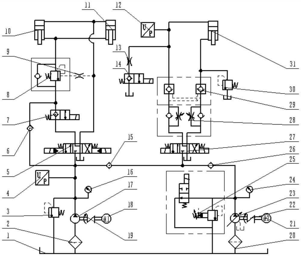
[0022] Hydraulic system for energy saving and low noise press, such as figure 1 As shown, the fuel tank 1; the first oil oil filter 2; the first straight-moving relief valve 3; the first pressure sensor 4; three four-flow electric hydraulic replace valve 5; first single-way valve 6; One or two two-way electromagnetic ball valve 7; external control one-way balancing valve 8; first anchor hole 9; movable plate driving long stroke hydraulic cylinder 10; movable plate driving hydraulic cylinder 11; second pressure sensor 12; second throttle Hole 13; second two-stage two-way electromagnetic ball valve 14; second single-way valve 15; first pressure table 16; internal meshing gear pump 17; AC servo motor 18; first coupling 19; second oil oil filter 20; three-phase asynchronous motor 21; second coupling 22; constant voltage variable plunger pump 23; second pressure table 24; e...
PUM
Abstract
The invention relates to an energy-saving, efficient and low-noise press hydraulic system. The system comprises an oil tank, a first oil suction filter, a first direct-acting overflow valve, a first pressure sensor, a three-position four-way electro-hydraulic reversing valve, a first one-way valve, a first two-position two-way electromagnetic ball valve, an external control one-way balance valve, a first throttling hole, a movable plate driving long-stroke hydraulic cylinder, a movable plate driving hydraulic cylinder, a second one-way valve, a first pressure gauge, an internal gear pump, an AC servo motor and a first coupling, a second pressure sensor, a second throttling hole, a second two-position two-way electromagnetic ball valve, a second oil suction filter, a three-phase asynchronous motor, a second coupler, a constant-pressure variable plunger pump, a second pressure gauge, an electromagnetic overflow valve, a third one-way valve, a three-position four-way electromagnetic reversing valve, a double one-way throttling valve, a two-way hydraulic lock, a second direct-acting overflow valve and a short-stroke pressurizing hydraulic cylinder. According to the system, the manufacturing difficulty is effectively reduced, the manufacturing cost is greatly reduced, the efficiency is high, the heat is little, and the noise is low.
Description
Technical field [0001] The present invention belongs to the field of hydraulic transmission and control, and involves a pressurized hydraulic system, especially a pressurized hydraulic system for energy saving and low noise. Background technique [0002] At present, hydraulic technology is widely used in various fields of the national economy, such as aviation, aerospace, ship, transportation, mechanical manufacturing, etc., and hydraulic components have achieved standardization, seriesization and generalization, greatly facilitating people's choices. [0003] The press is typically composed of a top and lower plate, an intermediate plate and a guide post. Because the press requires a larger output force, the up and down drive of the movable plate is generally realized by the hydraulic system. [0004] Traditional pressure machine hydraulic system, because high working pressure is usually used to do power sources with a plunger pump. The plunger pump is relatively large when the ...
Claims
Application Information
Patent Timeline
Application Date:The date an application was filed.
Publication Date:The date a patent or application was officially published.
First Publication Date:The earliest publication date of a patent with the same application number.
Issue Date:Publication date of the patent grant document.
PCT Entry Date:The Entry date of PCT National Phase.
Estimated Expiry Date:The statutory expiry date of a patent right according to the Patent Law, and it is the longest term of protection that the patent right can achieve without the termination of the patent right due to other reasons(Term extension factor has been taken into account ).
Invalid Date:Actual expiry date is based on effective date or publication date of legal transaction data of invalid patent.