Pile pulling construction method of pile pulling device

A construction method and technology of pile driver, applied in sheet pile wall, foundation structure engineering, construction and other directions, can solve the problems of difficult operation, low construction efficiency, long construction period, etc. short cycle effect

Active Publication Date: 2021-04-13
浙江万坚建设有限公司
View PDF5 Cites 0 Cited by
  • Summary
  • Abstract
  • Description
  • Claims
  • Application Information

AI Technical Summary

Problems solved by technology

At present, the commonly used method is to use destructive means such as hammering, rotary digging or twisting off the old pile foundation, and then clean up the remaining holes after destroying the waste pile body, which is time-consuming, laborious, long construction period, low construction efficiency, and large construction noise; or use The full casing adopts a clamp with spring control and other structures, which is clamped on the outer diameter of the waste pile after being penetrated to a certain depth, and then pulled upwards. However, it is difficult to control the clamping degree in actual operation, or the waste pile cannot be clamped to achieve the desired effect. The purpose of pulling out the whole waste pile is that the clamp is not tight enough to pull out the waste pile; or the full casing is used, and there are multiple sets of cutting components inside the full casing. After a certain depth, the cutting component is used to cut the waste pile first, and then the steel wire rope of the crane Manually fix the piles on the upper section to lift the waste piles out of the ground. This method has a lot of tool wear, many procedures, difficult operations for workers, low construction efficiency, and slow construction progress.
As far as the applicant knows, there is no ideal waste pile pulling device and method at present

Method used


Image

  • Pile pulling construction method of pile pulling device
  • Pile pulling construction method of pile pulling device
  • Pile pulling construction method of pile pulling device

Examples


Embodiment Construction

[0030] The specific embodiments of the present invention will be further described below in conjunction with the accompanying drawings. What needs to be declared here is that the descriptions of these specific implementations are used to help understand the present invention, but are not intended to limit the present invention. In addition, the technical features involved in the various specific embodiments of the present invention described below may be combined with each other as long as they do not constitute conflicts with each other.

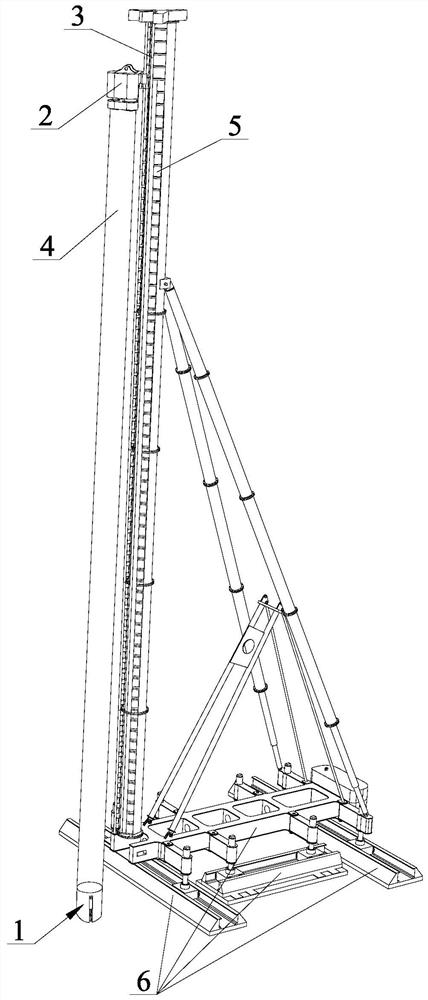
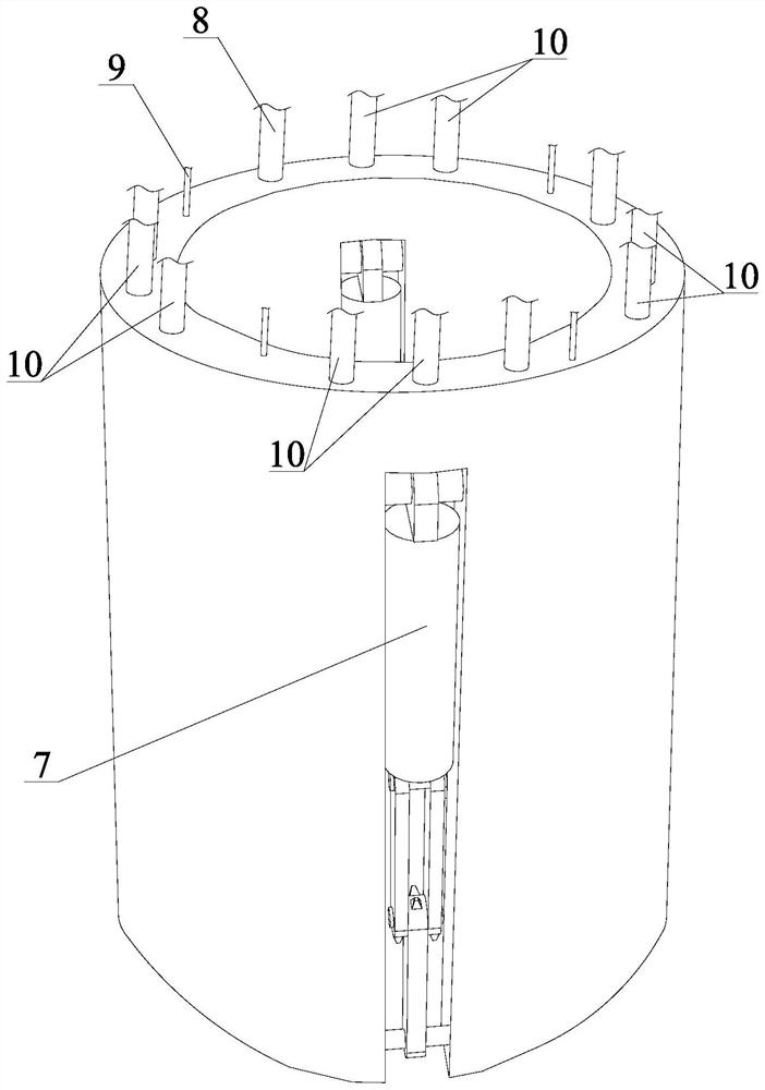
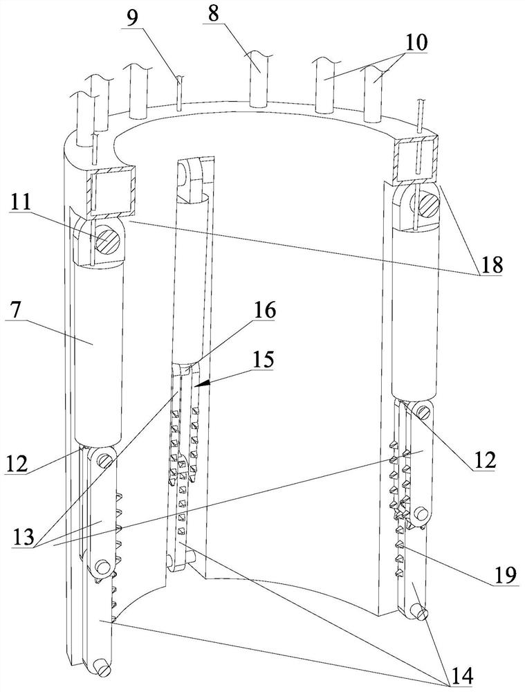
[0031] Such as figure 1 , figure 2 , image 3 , Figure 4 , Figure 5 shown

[0032]The pile pulling device of the present invention comprises a full casing 4 connected with the power head 2 of the combined power pile forming machine. Said connection can be in the prior art such as flange connection or quick joint connection. Described combined power hole-forming pile driver, such as the hydraulic walking pile driver of the prior ar...


PUM


Abstract

The invention discloses a pile pulling device and a pile pulling construction method thereof. There are multiple groups of claws on the pile device which are driven by the oil cylinder and can protrude toward the center of the pipe to form a plurality of claws that support or cut off the waste piles. There are several alloy teeth on the inner surface of the claws. The solenoid valve and oil pipe are connected to the oil pump and oil tank on the combined power pile machine; there are multiple high-pressure water nozzles at the bottom of the sleeve type pile extractor, and the high-pressure water nozzles are connected to the combined power hole forming machine through the solenoid valve and high-pressure water pipe. The pile driver is connected with the water pump of the water source; the oil cylinder is also provided with a distance sensor for detecting the downward elongation of the piston rod, and the distance sensor is electrically connected with the controller. The convex column is accurate and reliable for the bottom of the waste pile, the construction noise is small, and the waste pile is pulled out after one-time rotation or cutting, saving time and effort, the construction period is short, and the construction efficiency is high.

Description

technical field [0001] The invention relates to the technical field of waste pile cleaning, in particular to a pile pulling construction method of a pile pulling device. Background technique [0002] With the general promotion of urban expansion and renovation projects and the rise of urban rail transit construction, the cleaning of waste piles left after buildings were demolished in the 1980s and 1990s has become a technology that new high-rise buildings and urban rail transit must face. question. Generally, there are two situations: one is that the waste pile does not exceed 30 meters, and it can be pulled out at one time. The other is that although the waste pile is as long as 60 meters, it can meet the needs of rail transit construction, as long as the part above 30 meters is pulled out. At present, the commonly used method is to use destructive means such as hammering, rotary digging or twisting off the old pile foundation, and then clean up the remaining holes after ...

Claims


Application Information

Patent Timeline
Patent Type & Authority Patents(China)
IPC IPC(8): E02D9/02
CPCE02D9/02
Inventor 尚贤菊庄光明尚俏佳
Owner 浙江万坚建设有限公司
Why Eureka
Try Eureka