Ball jointed pedicle screw and rod system

a pedicle screw and ball jointed technology, applied in the field of screws, can solve the problems of inability to accurately place screws, cumbersome installation, unstable, expensive,

Inactive Publication Date: 2010-03-30
MUHANNA NABIL L
View PDF24 Cites 134 Cited by
  • Summary
  • Abstract
  • Description
  • Claims
  • Application Information

AI Technical Summary

Benefits of technology

[0009]In yet another aspect, the present invention is directed to a method of securing a rod in an orthopedic procedure. The method comprises seating a compressible hollow object in a screw having th...

Problems solved by technology

Part of the reason for this misalignment is natural anatomy of the spine, and part is the inability to accurately place screws where they would ideally be placed because of adjacent tissue, weak points in the vertebrae structure, and also because screws may not always be placed evenly in several levels.
These multiaxial screws and clamps...

Method used


Image

  • Ball jointed pedicle screw and rod system
  • Ball jointed pedicle screw and rod system
  • Ball jointed pedicle screw and rod system

Examples


Embodiment Construction

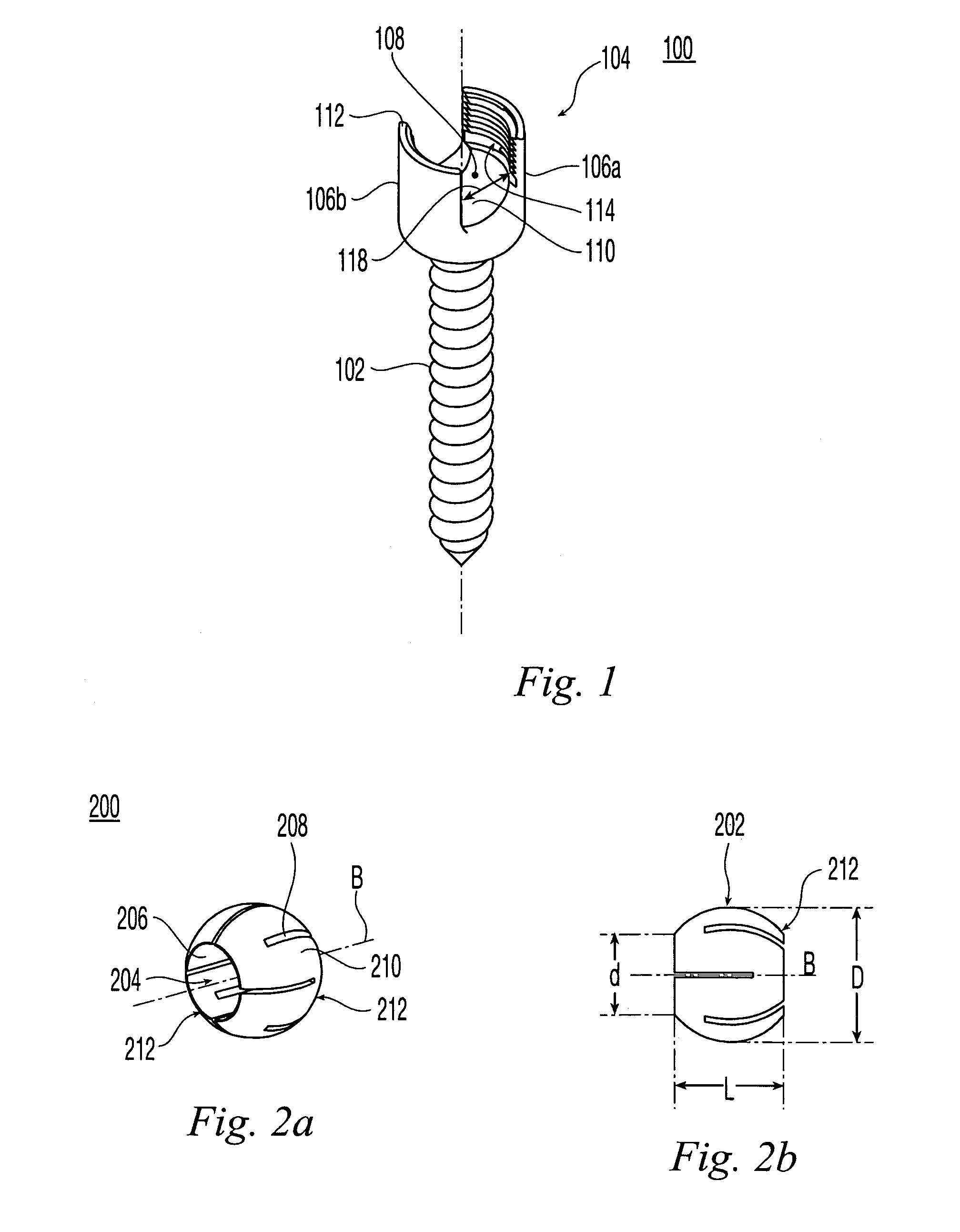
[0023]FIG. 1 shows a pedicle screw 100 in accordance with present invention. Pedicle screw 100 has a longitudinal axis along which a threaded insertion portion 102 is aligned. The top of the threaded insertion portion is connected to a yoke portion 104. Yoke portion 104 comprises a plurality of spaced apart threaded posts 106a, 106b separated by a circumferential gap 118 and defining a substantially cylindrical channel 108 therebetween. At the base of the channel 108, the pedicle screw 100 is provided with a concave seat 110 having a spherical contour. The posts 106a, 106b extend in a direction away from the threaded insertion portion 102, the end portions of the ports terminating in radially inwardly facing threads 112 formed on the posts' inner surfaces 114. Pedicle screw 100 preferably is formed of titanium, or an alloy thereof.

[0024]Preferably, the threaded insertion portion 102 and the yoke portion 104 have unitary construction, being formed from a single piece of metal, and so...


PUM


Abstract

A pedicle screw assembly includes pedicle screw having a plurality of spaced-apart posts. A ball collet having a ball collet bore is seated on the pedicle screw between the posts and a rod is gripped by an inner surface of the ball collet bore. The assembly also includes a cap that is coupled to the posts, the cap applying a compressive force to the ball collet against a seat of said pedicle screw. A free end of the rod may be provided with various structures to enable such free end to be retained by another pedicle screw.

Description

FIELD OF THE INVENTION[0001]The present invention is related to screws, such as those used in orthopedic surgery, and associated rods connecting such screws.BACKGROUND[0002]After a patient undergoes lumbar spinal disc surgery, there is a need to install pedicle screws and stabilizing rods to support the vertebrae during the fusion process that takes place in the weeks after surgery. Pedicle screws are inserted into the vertebrae in positions or axes that are typically not in a straight line. Part of the reason for this misalignment is natural anatomy of the spine, and part is the inability to accurately place screws where they would ideally be placed because of adjacent tissue, weak points in the vertebrae structure, and also because screws may not always be placed evenly in several levels. To compensate for this misalignment, the screws have to be jointed, the heads must swivel and rotate, attachments have to be installed, and invariably the rods themselves have to be bent in a 3-d...

Claims


Application Information

Patent Timeline
IPC IPC(8): A61B17/70
CPCA61B17/7005A61B17/7032A61B17/704
Inventor MUHANNA, NABIL L.SCHALLIOL, DAVID L.
Owner MUHANNA NABIL L
Why Eureka
Try Eureka