Orthopedic implant

a technology of orthopedic implants and implants, applied in the field of orthopedic implants, can solve the problems of increasing the chance of fracture, bulge or rupture, and reducing the size and strength

Inactive Publication Date: 2003-02-18
DEPUY ACROMED INC
View PDF134 Cites 564 Cited by
  • Summary
  • Abstract
  • Description
  • Claims
  • Application Information

AI Technical Summary

Problems solved by technology

When a bone is stress shielded, it typically reduces in size and strength according to Wolf's Law, increasing the chance of breakage.
Disc collapse or narrowing reduces the space between vertebrae, and damage to the disc can cause it to bulge or rupture, possibly extruding into the spinal canal or neural foramen.
These changes can cause debilitating back and distal pain, numbness, or weakness.
Both spinal fusion, such as disclosed by Michelson, and the use of spacers, such as disclosed by Biedermann, limit the mobility of the spine by fixing two adjacent vertebra relative to one another.
In addition to reduced mobility, these arrangements do not compensate for the shock absorption lost when a disc is damaged or removed.
However, the complex load bearing behavior of a disc has not been successfully reproduced with an elastomer, and such implants are prone to wear and failure.
These implants are subject to failure by rupture or drying out, just like a disc.
In addition to failing to accurately perform the functions of the replaced disc, these structures are multi-component and particles due to wear of articulating components can result in adverse biological responses or increase the possibility of mechanical failure.
This results in a significant portion of the proximal portion of the femur no longer experiencing a normal stress condition.
This condition will then result in a loss of bone mass surrounding the distal portion of the device.
Consequences of this bone loss include loss of support for the device, which will allow the device to move and become painful, and, should revision of the device required, then there may be insufficient bone for support of the subsequent implant.
None of these approaches have been successful in that the compromises required to achieve the reduction in stiffness did not find the proper compromise between the required strengths and stiffness.
While this material has excellent wear properties, it is not a wear free surface.
Instead the materials articulate directly on one other resulting in the generation of wear debris and possibly adverse biological responses.
However none of these approaches have been successful in reproducing the functionally graded material properties required for this application.
These methods have limitations regarding the size and shape of the features that may be produced.
Conversely, stresses not parallel to, or directly above, the struts will result in bending of the struts due to their flexibility.
Accordingly, if torsional supports 300A, 300B do not provide sufficient resistance to bending and rotation, implant 10 may allow over-rotation or excessive bending of a joint, potentially resulting in injury.
For example, where implant 10 is used to replace a spinal disc, over rotation or excessive bending could result in pain or damage to the nerves of the spinal column.
However, one possible disadvantage of manufacturing torsional supports 300A, 300B separately from plates 100, 102, in other words other than as a unitary structure, is that the points of attachment may weaken and be subject to fatigue and possibly failure.
Furthermore, if the struts are bent or twisted once formed, this deformation may result in micro-cracking and other structural degradation.

Method used


Image

  • Orthopedic implant
  • Orthopedic implant

Examples


Embodiment Construction

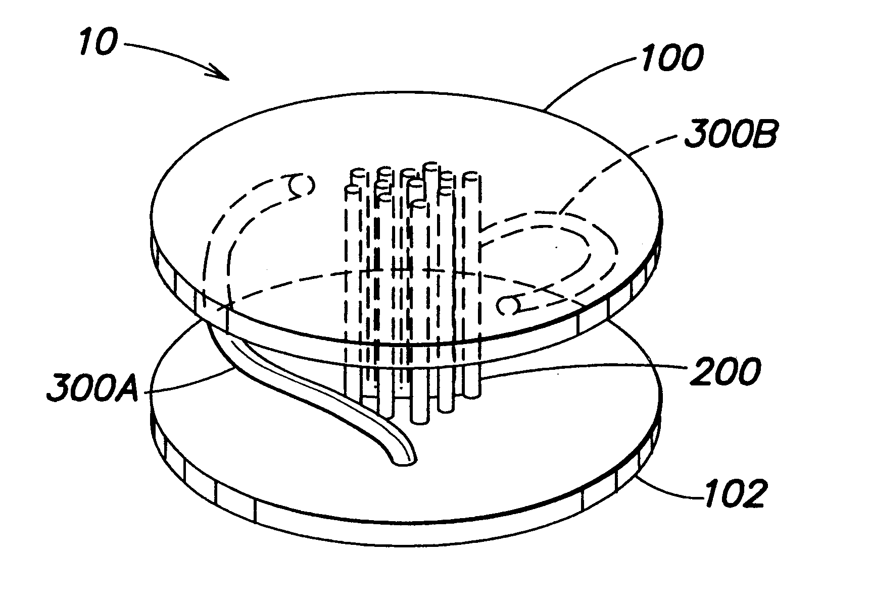
One suitable construction of an implant having a shape and design substantially in accordance with the present invention is provided by the following combination of elements.

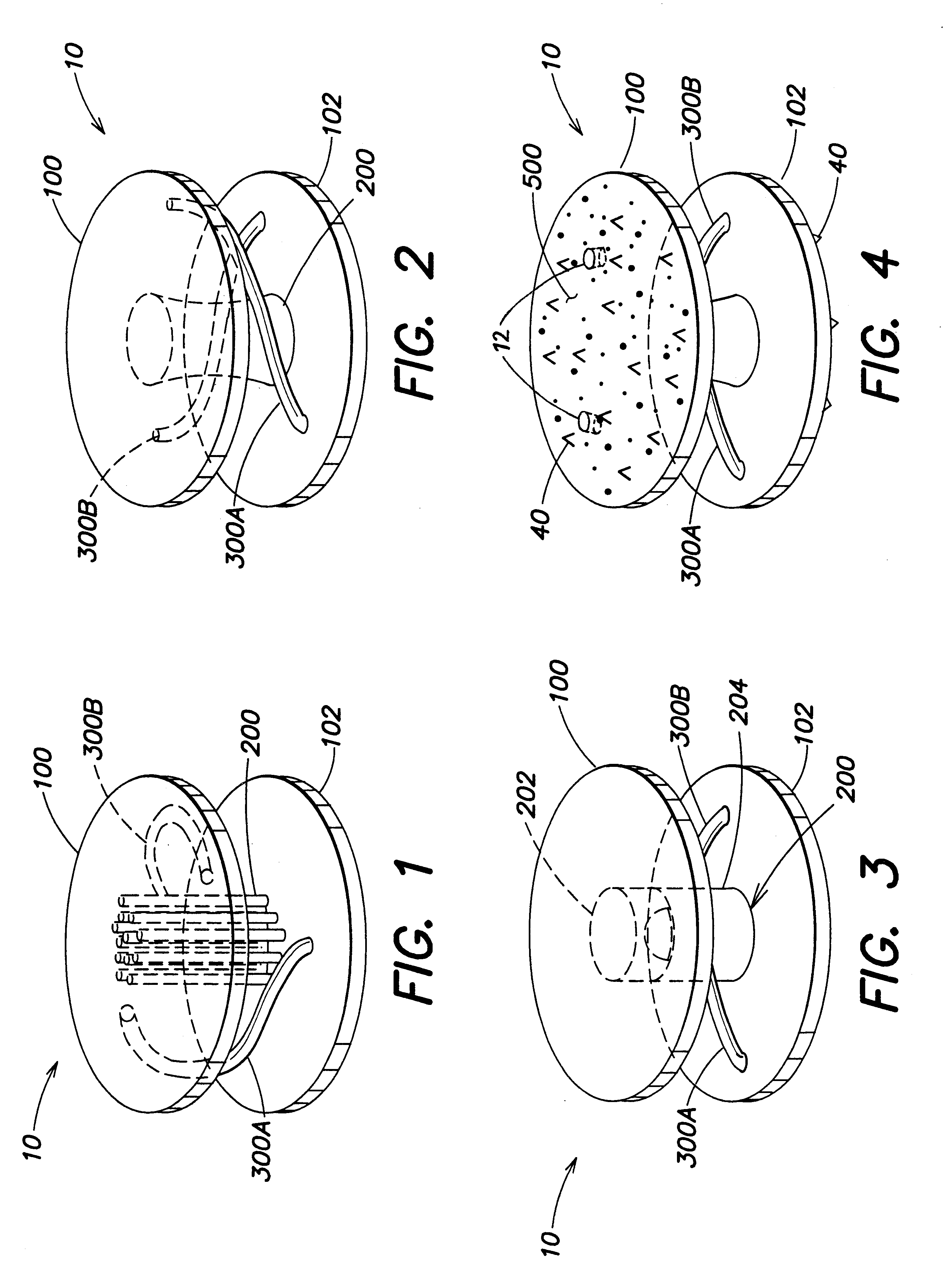
An implant 10 to be used in a spinal arthroplasty includes a first plate 100 and a second plate 102. Plates 100, 102 are substantially oval and planar and are sized to fit within a human spinal column in a space previously occupied by a disc. The outer planar surfaces of plates 100, 102 are provided with protrusions 400 consisting of teeth and a tissue ingrowth region 500 consisting of a textured surface.

Implant 10 also includes an axial support 200, between, and connecting, plates 100, 102. Axial support 200 is oriented in the center of plates 100, 102 and includes a cable incorporated at both ends to plates 100, 102. Implant 10 further includes two torsional supports 300A, 300B. Torsional supports 300A, 300B are integrally formed with plates 100, 102 and curve around axial support 200 such that the first end o...


PUM

PropertyMeasurementUnit
stressaaaaaaaaaa
heightaaaaaaaaaa
heightaaaaaaaaaa

Abstract

Disclosed is an orthopedic implant suitable for arthroplasty procedures. The orthopedic implant includes a first plate, a second plate, an axial support between the first plate and the second plate and one or more torsional supports connecting the first plate and the second plate. The axial support may be, for example, one or more flexible struts, such as cables, or a ball and socket joint. The torsional supports connect the first and second plates and may be, for example, curved around the axial support. The torsional supports may be integrally formed with the first and second plates as a single unitary device, by, for example, a Laser Engineered Net Shape (LENS) process.

Description

The present invention is directed to an orthopedic implant. More specifically, the orthopedic implant is suitable for arthroplasty procedures where optimized multifunctional behavior of the implant is desired. The implant may include the ability for load sharing between the implant and host bone, and the restoration of motion, such as in the replacement of a spinal disc.DESCRIPTION OF THE RELATED ARTOrthopedic implants have been used in the past to repair damage to the skeleton and related structures, and to restore mobility and function. For example, various devices, such as pins, rods, surgical mesh and screws, have been used to join fractured bones in the proper orientation for repair.Implants that restore the function to a damaged joint have also been used. Surgery intended to restore function to a joint is referred to as arthroplasty. A successful arthroplasty may eliminate pain and prevent the degradation of adjacent tissue. Arthroplasty has been performed on knees, hips and s...

Claims


Application Information

Patent Timeline
Patent Type & Authority Patents(United States)
IPC IPC(8): A61F2/44B22F3/105B29C67/00A61B17/86A61B17/68A61F2/00A61F2/30
CPCB22F3/1055A61F2/442A61F2002/30892A61F2002/30841A61F2002/3092A61F2002/30968A61F2002/3097A61F2002/30971A61F2002/443A61F2220/0025A61F2220/0075A61F2230/0004A61F2230/0008A61F2230/0069A61F2250/0018A61F2250/0029A61F2310/00023A61F2310/00179B29C67/0051B29L2031/7532A61B17/86A61F2/3094A61F2/30942A61F2/30965A61F2/4425A61F2002/30014A61F2002/30018A61F2002/30085A61F2002/30125A61F2002/30135A61F2002/30225A61F2002/30329A61F2002/30462A61F2002/30563A61F2002/30565A61F2002/30571A61F2002/30662A61F2002/30777A61F2002/30785A61F2002/30904B33Y80/00A61F2002/30084A61F2002/30136Y02P10/25B22F10/25B22F10/28
Inventor MANASAS, MARKOSLAKOVIC, KEITHSULTAN, CORNELHAMILTON, JOHNINGBER, DONALD
Owner DEPUY ACROMED INC
Why Eureka
Try Eureka