
Targeted geophysical survey

a geophysical survey and target technology, applied in the field of seismic surveying, can solve problems such as insufficient satisfactorily

Active Publication Date: 2010-03-30
PGS AMERICA INC
View PDF3 Cites 12 Cited by
  • Summary
  • Abstract
  • Description
  • Claims
  • Application Information

AI Technical Summary

Problems solved by technology

For areas of low illumination, the “fold”, i.e., the number of received seismic data traces representative of the areas of low illumination may be inadequate to satisfactorily map such locations.

Method used


Image

  • Targeted geophysical survey
  • Targeted geophysical survey
  • Targeted geophysical survey

Examples


Embodiment Construction

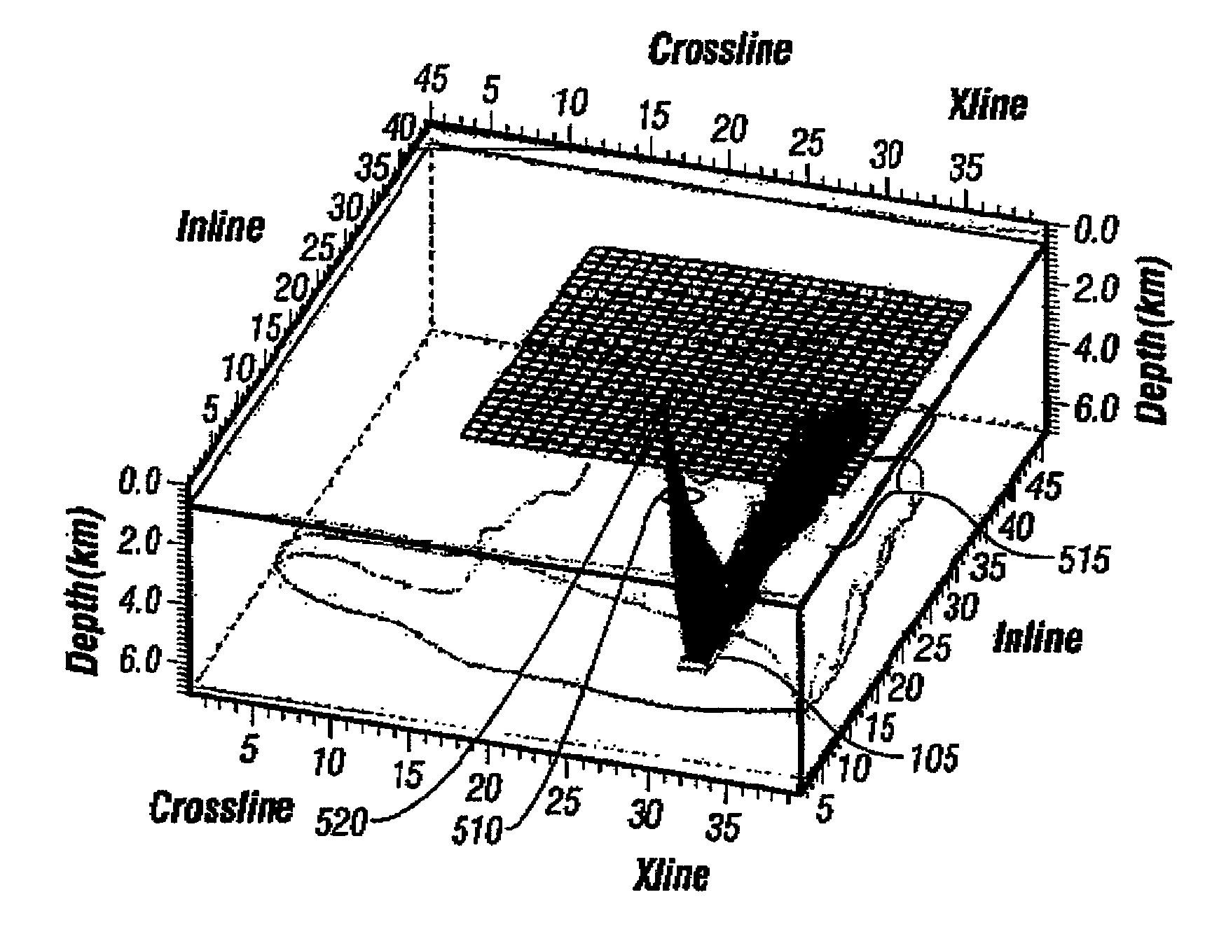
[0025]In practicing the present invention, a model of the subsurface, including a model of a target interface, and a velocity model of the subsurface strata between the earth's surface and the target interface, is utilized. The model shown in FIG. 4 shows such a model of a target interface.

[0026]The method of this invention is applicable to surveys in which a first survey may have been performed and resulted in an area of low illumination. The method of this invention is also applicable to processes in which a model of the subsurface has been generated from well log data, gravity data or magnetic data, as well as from a seismic survey, and to models that may have been created from varying combinations of seismic, well log, gravity and / or magnetic data, in which the model shows a subsurface structure that would result in a low illumination of such structure by standard seismic source and receiver placement.

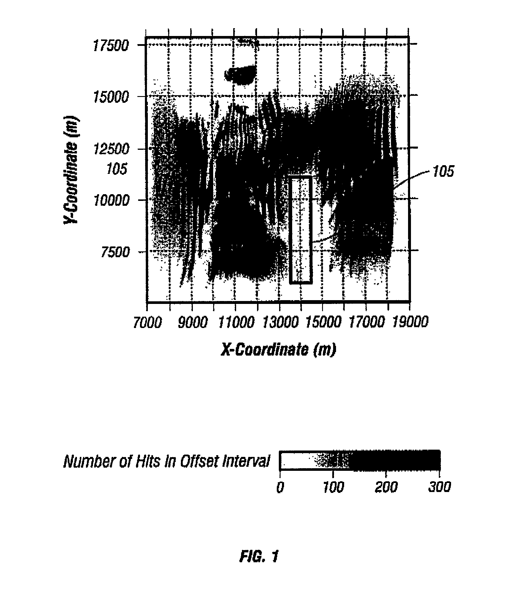
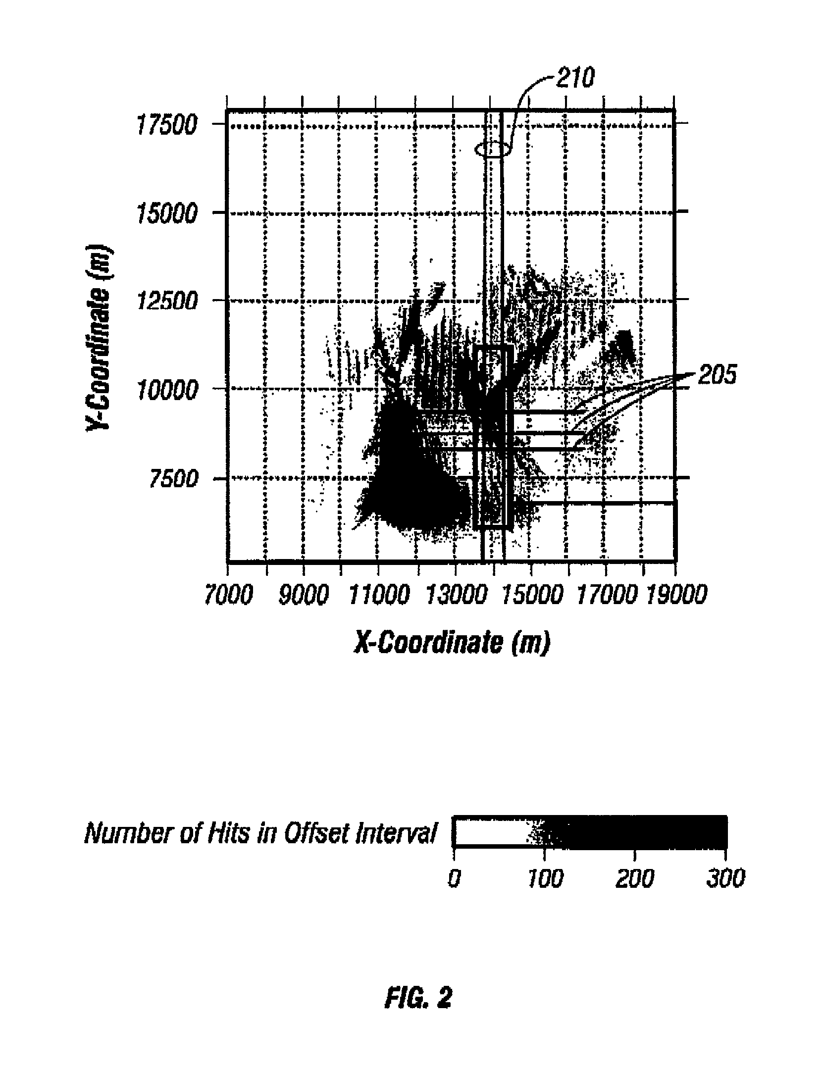
[0027]FIG. 1 is a map view of a targeted subsurface horizon showing the illumi...


PUM


Abstract

In one embodiment the invention comprises a system for planning a seismic survey based on a model of a subsurface formation in which a computer simulation is generated having sources and receivers positioned in selected locations with respect to the model. Ray tracing is performed from the sources to estimate a propagation ray path of seismic signals emanating from the source locations, and emergent points are determined at which ray paths reach the earth's surface following reflection from a subsurface area of interest. A survey may then be designed and performed in which receiver positions are concentrated at the areas where the emergent points are concentrated.

Description

CROSS-REFERENCE TO RELATED APPLICATIONS[0001]Not applicableSTATEMENT REGARDING FEDERALLY SPONSORED RESEARCH OR DEVELOPMENT[0002]Not applicableBACKGROUND OF THE INVENTION[0003]1. Field of the Invention[0004]The invention relates generally to the field of seismic surveying. More particularly, the invention relates to methods for planning and performing seismic surveys.[0005]2. Background Art[0006]Seismic surveying is known in the art for determining structures of rock formations below the earth's surface. Seismic surveys are performed by generating seismic signals at source locations and receiving the resulting seismic signals at receiver locations. The seismic signal emanates from the source, and spreads outwardly in a substantially spherical pattern. When the signal reaches interfaces in the subsurface between strata having different acoustic velocities (and also different acoustic impedances), a portion of the energy will be reflected from the interface, and a portion of the energy...

Claims


Application Information

Patent Timeline
Patent Type & Authority Patents(United States)
IPC IPC(8): G06G7/50G01V1/20G01V1/28
CPCG01V1/20G01V1/282G01V2210/614G01V2210/671
Inventor CAMPBELL, STEVEN BLAKE
Owner PGS AMERICA INC
Learn More