Supercharge Your Innovation With Domain-Expert AI Agents!

Gas turbine floating collar arrangement

a technology of floating collars and turbines, which is applied in the direction of combustion process, jet propulsion plants, lighting and heating apparatus, etc., can solve the problems of radial cracks, cracks in floating collar assemblies, and wear and heat on the collar, so as to reduce the occurrence of cracks

Active Publication Date: 2010-04-06
PRATT & WHITNEY CANADA CORP
View PDF24 Cites 19 Cited by
  • Summary
  • Abstract
  • Description
  • Claims
  • Application Information

AI Technical Summary

Problems solved by technology

The collar is subject to wear and heat.
Radial cracks occur around the fuel nozzle hole, and floating collar assemblies crack due to the metal being exposed to hot air.
One cause of the cracking is that the thermal barrier coating, applied on the inner surface of the combustor wall near the fuel nozzle hole, cannot be brought to the edge of the fuel nozzle hole to protect the metal due to weld contamination.
In addition, the welds are exposed to hot air, which inevitably results in cracking.

Method used


Image

  • Gas turbine floating collar arrangement
  • Gas turbine floating collar arrangement
  • Gas turbine floating collar arrangement

Examples


Embodiment Construction

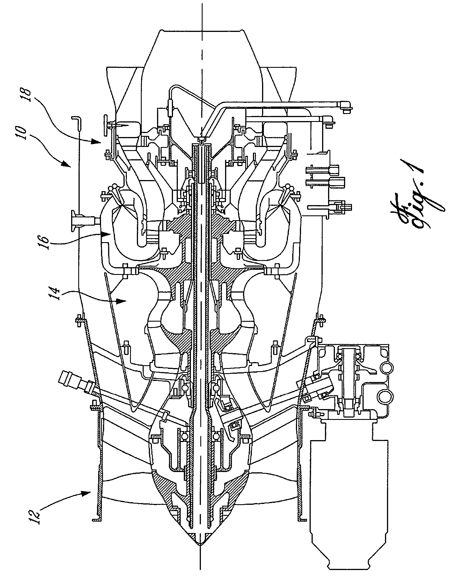
[0013]FIG. 1 illustrates a gas turbine engine 10 of a type preferably provided for use in subsonic flight, generally comprising in serial flow communication a fan 12 through which ambient air is propelled, a multistage compressor 14 for pressurizing the air, a combustor 16 in which the compressed air is mixed with fuel and ignited for generating an annular stream of hot combustion gases, and a turbine section 18 for extracting energy from the combustion gases.

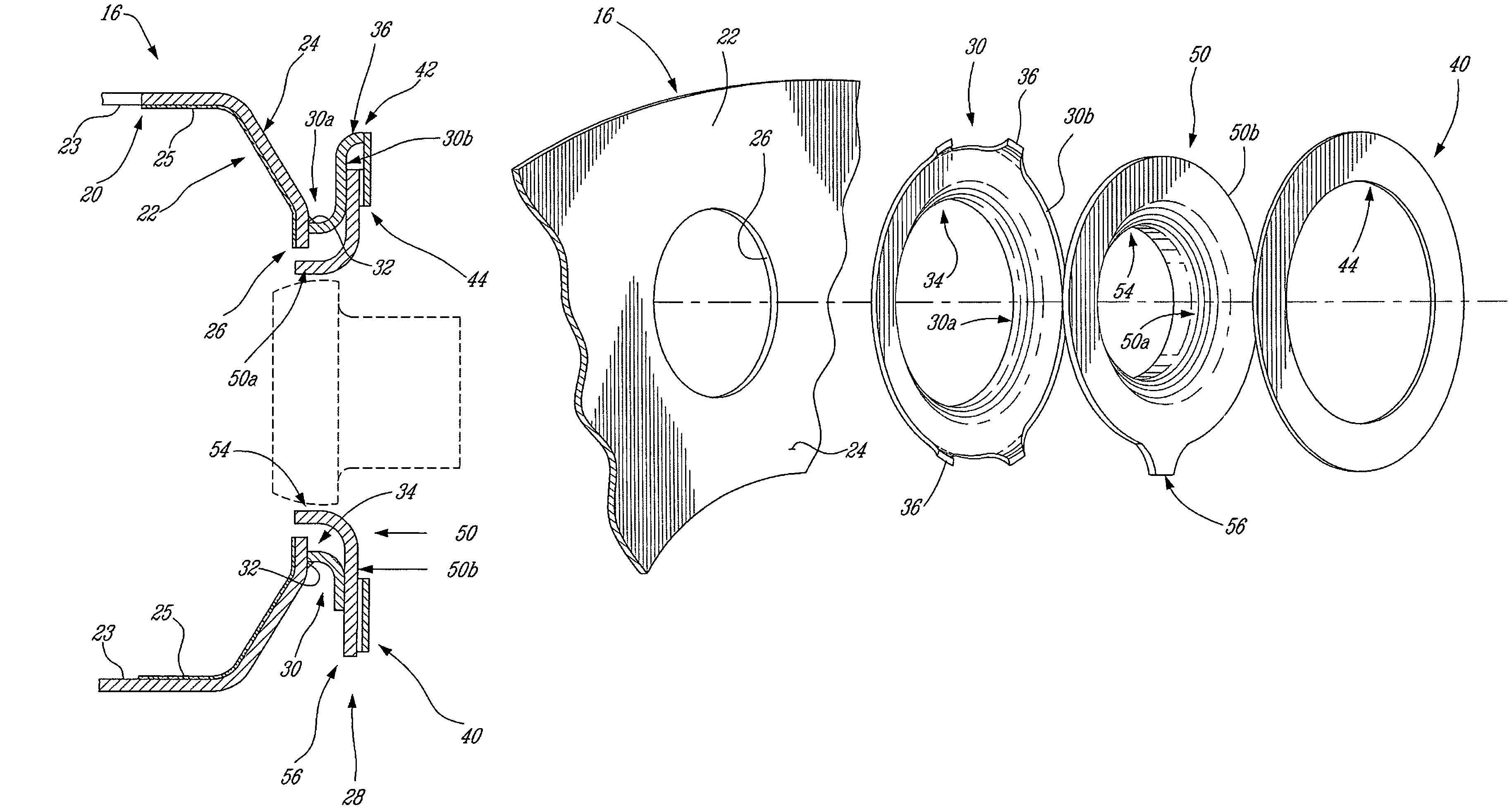
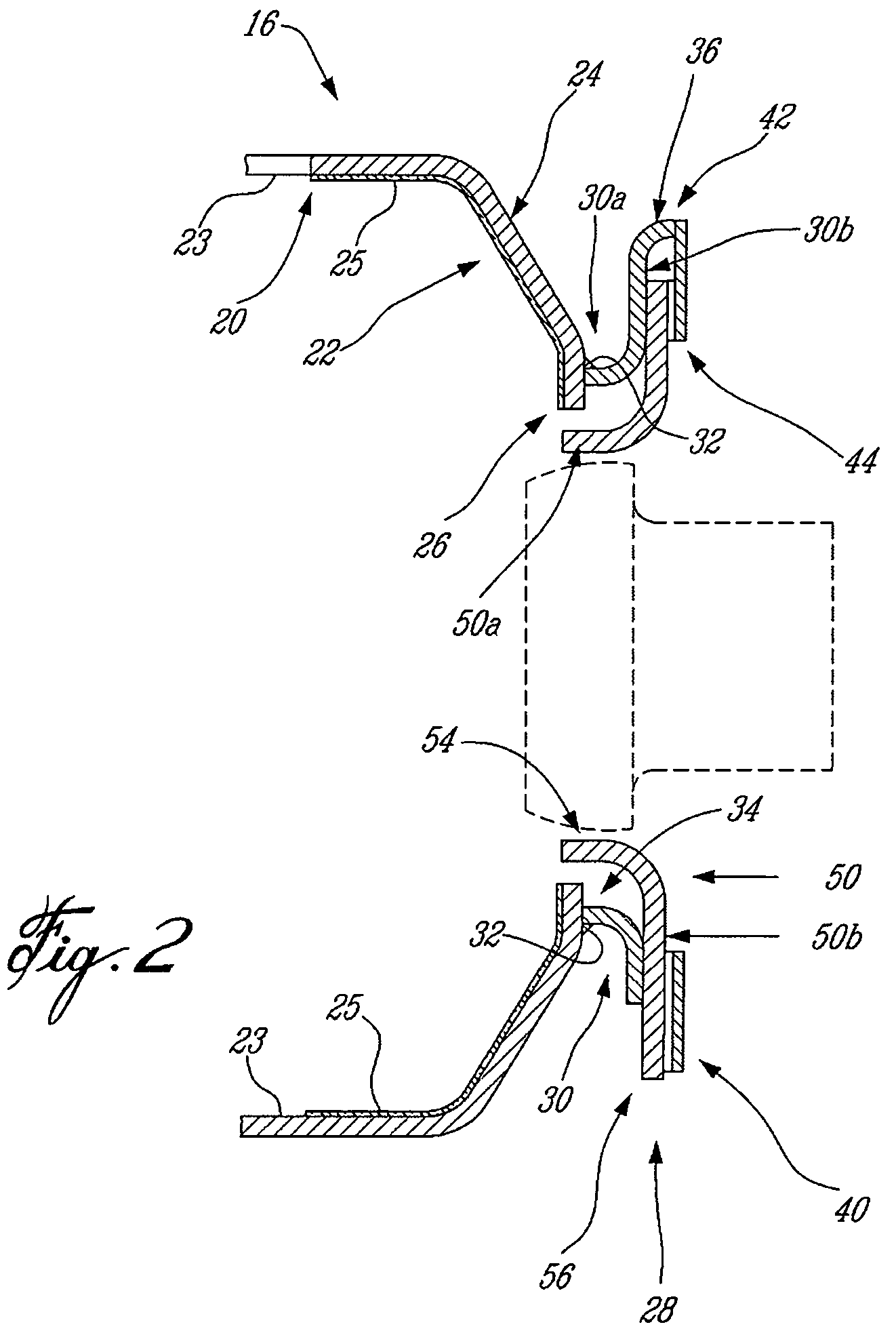
[0014]FIG. 2 shows an enlarged axial sectional view of an annular combustor 16 comprising a combustor wall or liner 20 defining a dome 22 having inner and outer surfaces 23 and 24 and a circumferential array of central fuel nozzle openings (only one being shown at 26) for receiving a plurality air swirler fuel nozzles (one being depicted in stippled lines in FIG. 2) of the type generally described in U.S. Pat. Nos. 6,289,676 or 6,082,113, for example, and which are incorporated herein by reference. Each fuel nozzle is associate...


PUM


Abstract

A crack-resistant floating collar mounting arrangement is provided comprising a collar mounted between spaced-apart mounting flanges, the flange being fixed to a dome from an outer surface unexposed to the hot combustor temperatures.

Description

CROSS-REFERENCE TO RELATED APPLICATIONS[0001]This is a Continuation-In-Part of application Ser. Nos. 10 / 924,208 now U.S. Pat. No. 7,134,286 and Ser. No. 10 / 924,209 now U.S. Pat. No. 7,140,189 both filed on Aug. 24, 2004.TECHNICAL FIELD[0002]The invention relates generally to gas turbine engine combustors and, more particularly, to a floating collar arrangement therefor.BACKGROUND OF THE ART[0003]Gas turbine combustors are typically provided with floating collars or seals to permit relative radial or lateral motion between the combustor and the fuel nozzle while minimizing leakage therebetween. The collar is typically welded to the edge of a fuel nozzle hole defined in the dome end portion of the combustor wall. The collar is subject to wear and heat. Radial cracks occur around the fuel nozzle hole, and floating collar assemblies crack due to the metal being exposed to hot air. One cause of the cracking is that the thermal barrier coating, applied on the inner surface of the combusto...

Claims


Application Information

Patent Timeline
Patent Type & Authority Patents(United States)
IPC IPC(8): F02C7/20
CPCF23R3/002F23R3/60F23R3/283F23R2900/00012
Inventor MARKARIAN, LORINPATEL, BHAWAN B.
Owner PRATT & WHITNEY CANADA CORP
Features
  • R&D
  • Intellectual Property
  • Life Sciences
  • Materials
  • Tech Scout
  • Unparalleled Data Quality
  • Higher Quality Content
  • 60% Fewer Hallucinations
Learn More