Drive axle with air passage for tire inflation system

Inactive Publication Date: 2010-04-06
ARVINMERITOR TECH
View PDF14 Cites 50 Cited by
  • Summary
  • Abstract
  • Description
  • Claims
  • Application Information

AI Technical Summary

Problems solved by technology

Drive axles present challenges for routing air from the air tanks to the tires.
Such a routing configuration takes up a significant amount of packaging space that could otherwise be

Method used


Image

  • Drive axle with air passage for tire inflation system
  • Drive axle with air passage for tire inflation system
  • Drive axle with air passage for tire inflation system

Examples


Embodiment Construction

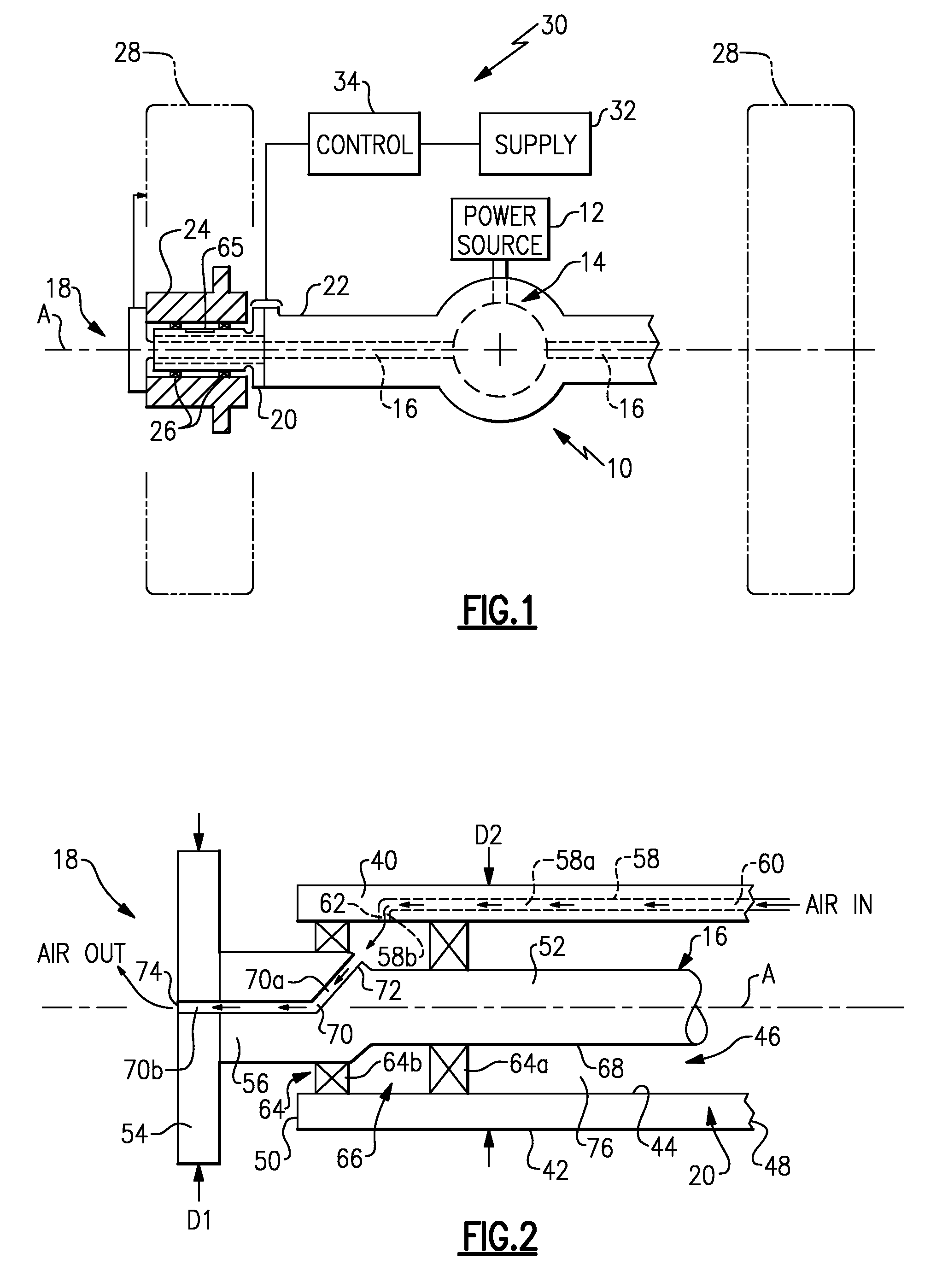
[0014]FIG. 1 shows a drive axle 10 receiving driving input from a power source 12, such as an engine or electric motor for example. The driving input drives an input gear assembly 14 that includes a differential mechanism as known. The gear assembly 14 drives axle shafts 16 that are coupled to drive wheel end assemblies 18. One example of a wheel end assembly 18 is shown to the left of FIG. 1. It should be understood that the opposite wheel end assembly 18 would be similarly formed.

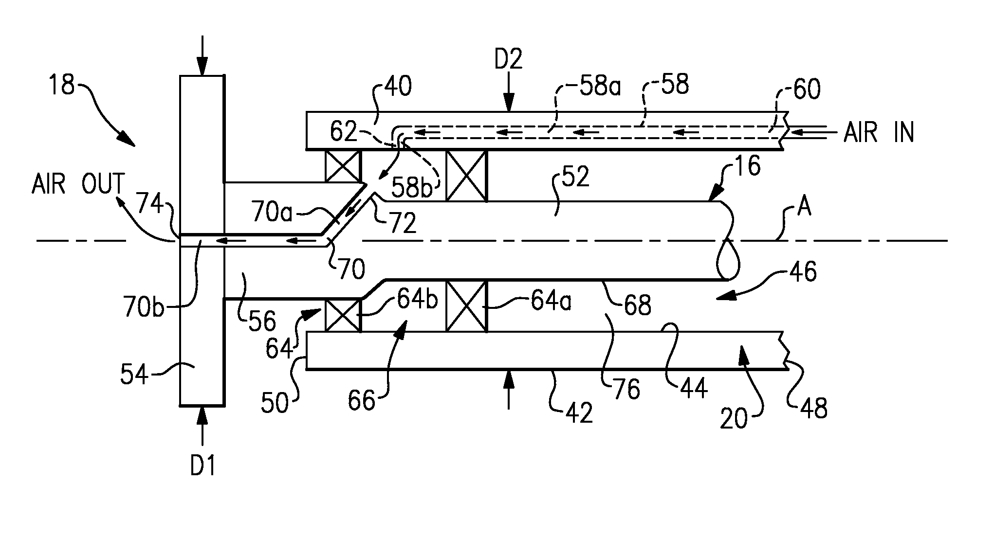
[0015]The wheel end assembly 18 includes a non-rotating spindle 20 that is mounted to an axle housing 22. The axle housing 22 houses the gear assembly 14 and axle shafts 16. A wheel hub 24 is rotatably supported on the spindle 20 by bearings 26. A tire 28 and associated rim are mounted for rotation with the wheel hub 24 about an axis A.

[0016]A tire inflation system 30 includes an air supply reservoir or tank 32 that is used to supply air to the tires 28 when the tires 28 become under-inflated. The tire in...


PUM


Abstract

A drive axle assembly includes a non-rotating spindle having a cylindrical body defining an internal cavity and an axle shaft assembly mounted within the internal cavity for rotation about an axis. A seal assembly is positioned within the internal cavity to provide a sealed chamber between the axle shaft assembly and the non-rotating spindle. A first air passage is formed within the cylindrical body and includes an air inlet to be in fluid communication with an air supply and an air outlet in fluid communication with the sealed chamber. A second air passage is formed within the axle shaft assembly and receives air input from the sealed chamber and includes an air output to be associated with at least one tire.

Description

TECHNICAL FIELD[0001]The subject invention relates to a drive axle that includes an air passage that forms part of a tire inflation system. More specifically, the air passage is formed at least in part between an axle shaft assembly and a spindle.BACKGROUND OF THE INVENTION[0002]Tire inflation systems are used on vehicles, such as tractor-trailer vehicles for example, to maintain tire inflation pressures at a desired tire pressure setting. The tire inflation system draws pressurized air from on-board air tanks and supplies this air to an under-inflated tire when tire pressure falls below the desired tire pressure setting.[0003]Drive axles present challenges for routing air from the air tanks to the tires. Typically, air hoses must be routed externally of the axle components and around the outside of the tires. Such a routing configuration takes up a significant amount of packaging space that could otherwise be used for other vehicle components. Further, due to the external mounting,...

Claims


Application Information

Patent Timeline
IPC IPC(8): B60C23/10
CPCB60C23/003B60C23/00336B60C23/00363B60C23/0039
Inventor JENKINSON, SCOTTTERTZAKIAN, JEREMYMILLER, STEVEN R.GONSKA, DAVIDELLIS, TRACY G.WITTRY, CHRISTOPHER J.MORGAN, JOHN D.DECAIRE, RICHARDAUSTIN, NORMAN D.WANG, YENKAI
Owner ARVINMERITOR TECH
Why Eureka
Try Eureka