Annuloplasty ring holder

a technology of annuloplasty and ring holder, which is applied in the field of annuloplasty, can solve the problems of limiting the surgeon's ability to securely abut an annuloplasty ring, limiting the surgeon's ability to effectively place attachment sutures through the ring, and the ring holding poin

Active Publication Date: 2010-04-06
MEDTRONIC INC
View PDF30 Cites 20 Cited by
  • Summary
  • Abstract
  • Description
  • Claims
  • Application Information

AI Technical Summary

Benefits of technology

[0011]Another embodiment of the present invention is an annuloplasty ring and holder combination. The annuloplasty ring holder may be as is described above. In the combination embodiment an annuloplasty ring is removably associated with the annuloplasty ring receiving surface of the head. This embodiment may include a ring suture as the mechanism for removably associating the annuloplasty ring to the head. Preferably, a single ring suture which is also securely attached to the head is used to secure the ring. In addition, a retaining suture may be used to removably associate the ring suture with the central hub. Preferably the retaining suture is tied and configured such that severance of the retaining suture in one place will allow the ring suture to be fully released from the ring.

Problems solved by technology

This is awkward as the ring holding point has to be frequently readjusted as the several implantation sutures are placed through the circumference of the ring body.
This configuration can in certain instances limit a surgeon's ability to securely abut an annuloplasty ring against a patient's annulus since the holder may interfere with proper positioning.
However the extended ring contact along a shaped circumferential supporting surface or channel can limit a surgeon's ability to effectively place attachment sutures through the ring.
Circumferential ring placement on a holder can also hinders efficient ring release after implantation.

Method used


Image

  • Annuloplasty ring holder
  • Annuloplasty ring holder
  • Annuloplasty ring holder

Examples


Embodiment Construction

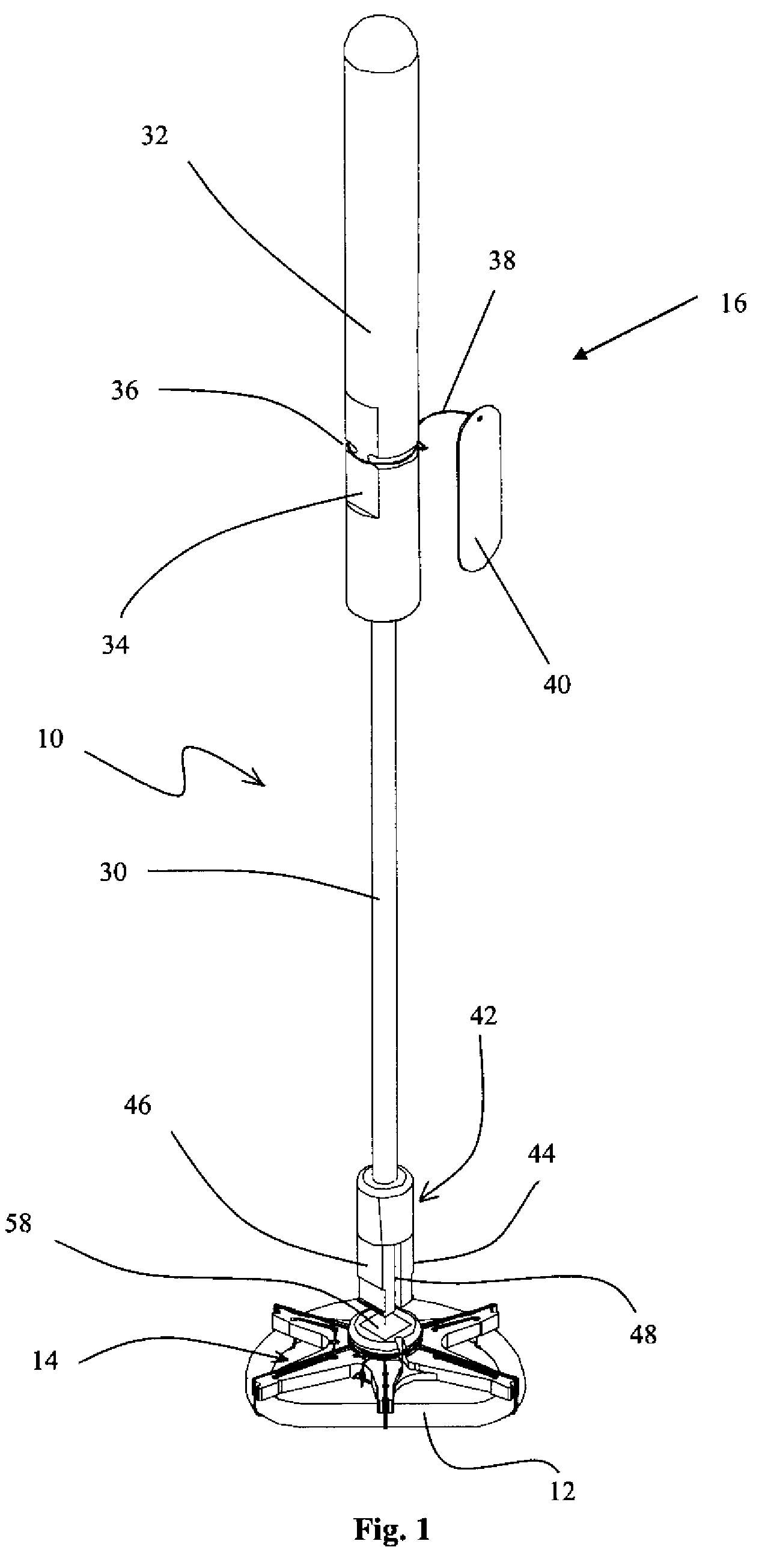
[0022]FIG. 1 is an isometric view of an annuloplasty ring holder 10 with an annuloplasty ring 12 attached. Although shown in FIG. 1 with a head 14 and a handle 16, the annuloplasty ring holder 10 of the present invention may be supplied as a head 14 only. Certain embodiments will include a handle 16, the invention is not however limited to such embodiments.

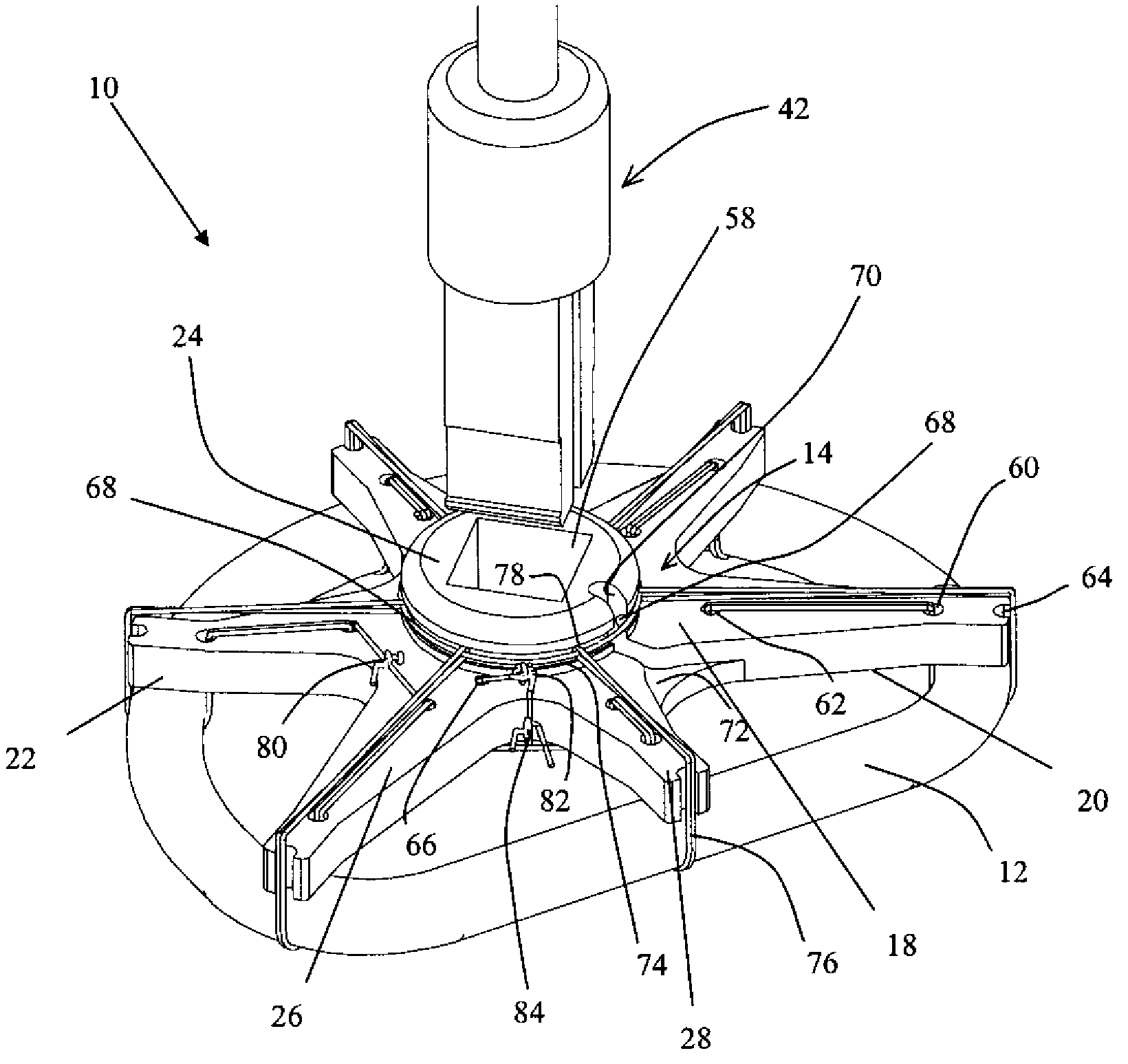
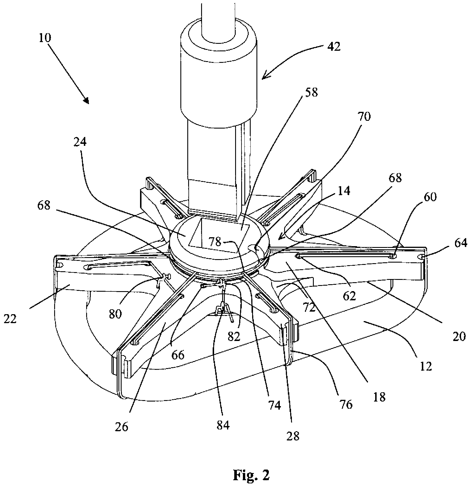
[0023]FIG. 2 is an isometric view of a holder 10 consistent with the present invention. The head 14 includes an upper surface 18 and an annuloplasty ring receiving surface 20 facing opposite the upper surface. The present invention is not limited to head 14 embodiments which are substantially planar, however in a planar implementation the upper surface 18 faces the handle 16 if a handle 16 is present. The annuloplasty ring receiving surface 20 is opposite the upper surface 18 and faces away from the handle 16. Positioned substantially between the upper surface 18 and the annuloplasty ring receiving surface 20 is a circumferential ...


PUM


Abstract

An annuloplasty ring holder including a head having an upper surface and an annuloplasty ring receiving surface facing opposite the upper surface. The annuloplasty ring holder also includes means for attaching an annuloplasty ring to the annuloplasty ring receiving surface. The means for attaching an annuloplasty ring to the annuloplasty ring receiving surface may include one or more suture guides operatively associated with the head and configured to position one or more sutures to removably associate an annuloplasty ring with the annuloplasty ring receiving surface. The head may include a central hub and more than one spoke radiating out from the central hub. If the head is thus configured, each spoke will include a portion of the annuloplasty ring receiving surface.

Description

RELATED APPLICATIONS[0001]This application claims priority from U.S. Provisional Patent Application Ser. No. 60 / 719,483, filed Sep. 21, 2005, entitled Annuloplasty Ring Holder.TECHNICAL FIELD[0002]The present invention is directed toward an annuloplasty ring holder and more particularly toward an annuloplasty ring holder with an annuloplasty ring receiving surface facing opposite an upper surface.Background Art[0003]Annuloplasty rings are used to stabilize and restrict the mitral or tricuspid annulus in heart valve repair surgery. There are several different types of annuloplasty rings in current clinical use. For example, the Carpentier-Edwards ring is a rigid “D” shaped semi-closed ring. The Cosgrove-Edwards band is a fully flexible “C” shaped ring, and the Medtronic-Duran ring is a fully flexible circular ring.[0004]Annuloplasty ring holders are particularly useful for use during implantation of flexible annuloplasty rings because of certain surgical attachment and positioning ch...

Claims


Application Information

Patent Timeline
Patent Type & Authority Patents(United States)
IPC IPC(8): A61F2/24
CPCA61F2/2466A61F2/2445A61F2240/001Y10S623/904
Inventor WRIGHT, JOHN T. M.NGUYEN, HIEU CONG
Owner MEDTRONIC INC
Why Eureka
Try Eureka