Optical system of portable projector and mobile communication terminal using the same

a portable projector and mobile communication technology, applied in the field of optical systems of projectors, can solve the problems of not only a large number of optical elements, excessive installation space, and the inability to reduce the entire so as to reduce the overall size of the projector, minimize the optical system space, and minimize the path of light

Active Publication Date: 2010-04-13
LG ELECTRONICS INC
View PDF23 Cites 1 Cited by
  • Summary
  • Abstract
  • Description
  • Claims
  • Application Information

AI Technical Summary

Benefits of technology

[0019]An object of the present invention is to provide an optical system of a portable projector, which has a novel arrangement capable of minimizing the space of the optical system, thereby achieving a reduction in the overall size of the projector, and a mobile communication terminal using the same.
[0020]Another object of the present invention is to provide an optical system of a portable projector, which can minimize the path of light, thereby achieving a reduction in the loss of light, and a mobile communication terminal using the same.
[0021]Yet another object of the present invention is to provide an optical system of a portable projector, which can achieve a stabilized arrangement of optical elements, and a mobile communication terminal using the same.
[0032]The optical elements may include: at least one light splitter supported on the first surface of the member for transmitting a specific wavelength of the light beams emitted from the light source device; a first lens placed on a surface of the light splitter facing the light source device for diffracting the light beams emitted from the light source device; a plate placed on a surface of the first lens facing the light source device, and having an irregular surface pattern for removing speckle noise of the light beams emitted from the light source device; and at least one second lens supported on at least one of the first and second surfaces of the member for diffracting the light beams emitted from the light splitter, to emit the diffracted light beams to the scan mirror.

Problems solved by technology

The conventional projectors having the above-mentioned arrangement, however, have a problem in that they require not only a great number of optical elements, but also an excessively large installation space due to a three dimensional arrangement of an optical system thereof.
Such an arrangement of the optical system makes it impossible to reduce the entire size of the projector.
Also, the conventional projectors generally suffer from the loss of light because a traveling path of the light from the light source to the projection lens unit is long.
Therefore, the conventional projectors have a limitation to display a bright and vivid image.
Due to the three dimensional arrangement of the optical system, furthermore, the conventional projectors have a problem in that an arrangement of optical elements is unstable.

Method used


Image

  • Optical system of portable projector and mobile communication terminal using the same
  • Optical system of portable projector and mobile communication terminal using the same
  • Optical system of portable projector and mobile communication terminal using the same

Examples


first embodiment

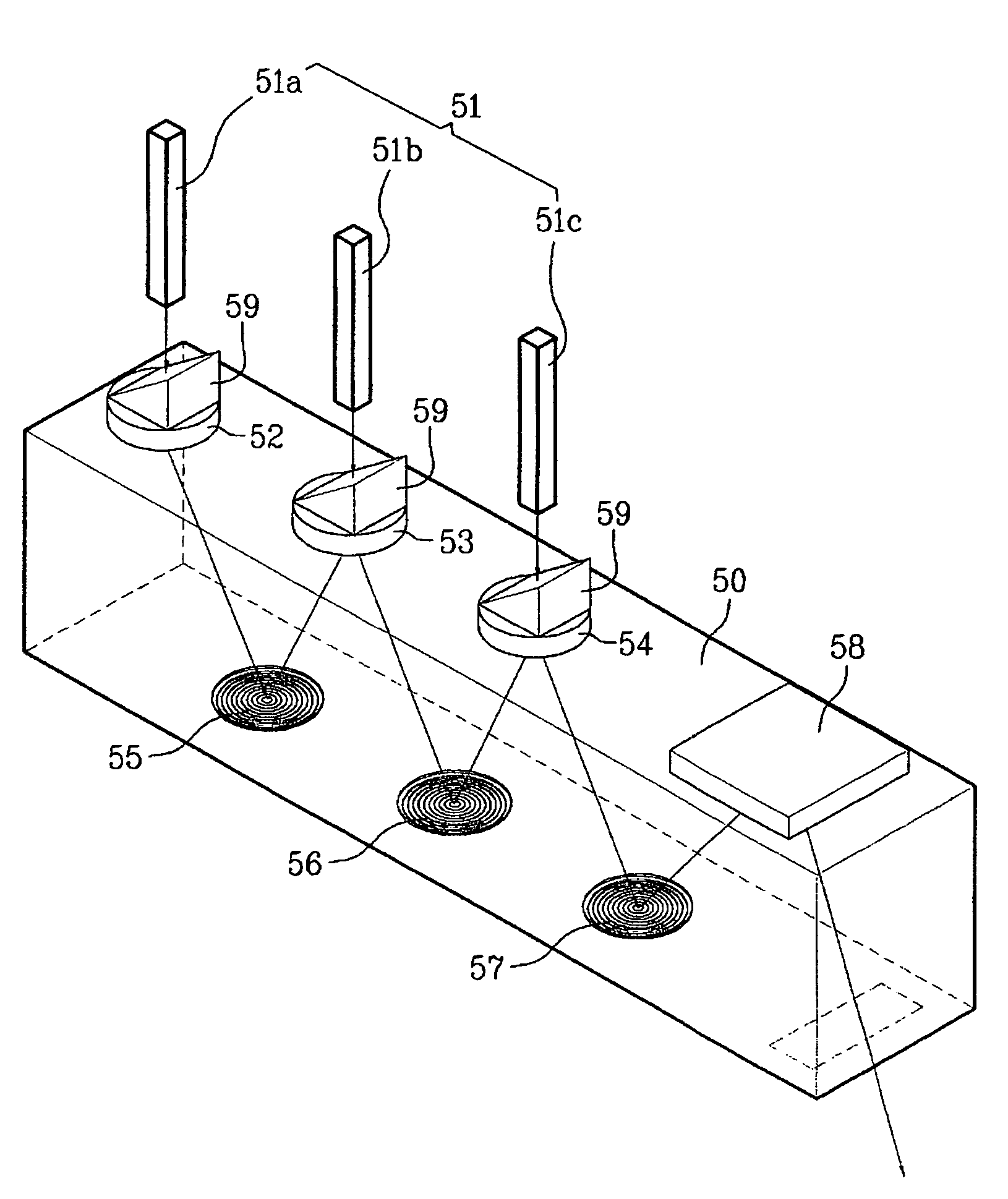
[0074]FIGS. 3A and 3B are perspective views illustrating an optical system of a portable projector in accordance with the present invention.

[0075]Specifically, FIG. 3A illustrates an optical system using a scan mirror, and FIG. 3B illustrates an optical system using a micro-display.

[0076]As shown in FIG. 3A, the portable projector of the present invention includes a light transmission member 50, a light source device 51, first, second, and third beam splitters 52, 53, and 54, first and second mirrors 55 and 56, a diffraction lens 57, a scan mirror 58, and a plurality of prisms 59.

[0077]The light transmission member 50 may be a glass member, transparent plastic member, or hollow member having an atmosphere or vacuum pressure interior. Of course, it should be understood that other materials may be used to form the light transmission member 50 so long as they have high light transmission efficiency, and the size of the light transmission member 50 may be determined based on the design ...

second embodiment

[0119]FIG. 5 is a perspective view illustrating an optical system of a portable projector in accordance with the present invention.

[0120]As shown in FIG. 5, the projector of the present invention includes the light transmission member 50, light source device 51, first, second, and third lenses 72, 73, and 74, first, second, and third mirrors 75, 76, and 77, a diffraction lens 78, and a scan mirror 79.

[0121]The first lens 72 may be a diffraction optical element (DOE) type lens. In accordance with the design of the optical system, a variety of DOE lenses are usable.

[0122]The first lens 72 is fabricated such that an upper surface thereof, onto which laser light beams are incident, has a different grating state from that of a lower surface thereof from which the laser light beams are emitted.

[0123]As shown in FIGS. 6A and 6B, the laser light beam incident surface of the first lens 72 has a grating angle for converging the laser light beams, whereas the laser light beam emitting surface ...

third embodiment

[0139]FIG. 7 is a perspective view illustrating an optical system of a portable projector in accordance with the present invention.

[0140]As shown in FIG. 7, in the third embodiment of the present invention, a speckle noise remover 80 is provided to remove noise of laser light beams.

[0141]The speckle noise remover 80 is placed on the first surface of the member 50.

[0142]The speckle noise removers 80 includes at least one light splitter 83, a lens 82 placed on the light splitter 83, and a plate 81 placed on the lens 82, the light splitter 83, lens 82, and plate 81 being integrally formed with one another.

[0143]The light splitter 83 is placed on the first surface of the member 50, and is used to transmit a specific wavelength of light beams emitted from the light source device 51.

[0144]The lens 82 is placed on a surface of the light splitter 83 facing the light source device 51, and is used to diffract the light beams emitted from the light source device 51.

[0145]Here, the lens 82 may ...


PUM


Abstract

An optical system of a portable projector and a mobile communication terminal using the same are disclosed. The optical system comprises a light transmission member having first and second surfaces, a light source device for emitting light beams onto the first surface of the member, so as to allow the light beams to be transmitted into the member, and one or more optical elements supported on at least one of the first and second surfaces of the member for diffracting the light beams incident from the light source device into the member, and subsequently reproducing and emitting an image from the diffracted light beams, to the outside of the member.

Description

[0001]This application claims the benefit of the Korean Patent Application No. 10-2005-0038394 filed on May 9, 2005, 10-2005-0080894 filed on Aug. 31, 2005 10-2005-0080895 filed on Aug. 31, 2005, 10-2005-0080899 filed on Aug. 31, 2005, 10-2005-0080898 filed on Aug. 31, 2005, 10-2005-0080897 filed on Aug. 31, 2005, 10-2005-0089974 filed on Sep. 27, 2005 and 10-2005-0091338 filed on Sep. 29, 2005 which is hereby incorporated by reference as if fully set forth herein.BACKGROUND OF THE INVENTION[0002]1. Field of the Invention[0003]The present invention relates to an optical system of a projector, and more particularly, to an optical system of a portable projector and a mobile communication terminal using the same.[0004]2. Discussion of the Related Art[0005]The recent tendency of display devices is to provide a large screen size as well as lightness and thinness. Of such display devices, projectors have been greatly highlighted because they can realize a large screen of 100 inches or mor...

Claims


Application Information

Patent Timeline
Patent Type & Authority Patents(United States)
IPC IPC(8): G03B21/28G02B26/10G02B27/18G03B21/00G03B21/14H04M1/00H04N5/74
CPCG02B5/1819G02B13/0055G02B13/0065G02B27/4272G03B21/14H04N9/3197G03B29/00H04N9/3129H04N9/315G03B21/28H04N5/74G03B21/2033G03B21/2066G03B21/208
Inventor SHIN, SUNG-CHUL
Owner LG ELECTRONICS INC
Why Eureka
Try Eureka