Electrical switching apparatus and stored energy assembly therefor

a technology of electrical switching apparatus and stored energy, which is applied in the direction of snap-action arrangement, protection switch operating/release mechanism, high-tension/heavy-dress switch, etc., can solve the problems of difficult repair, replacement and/or maintenance of charging mechanism, relative complexity of making and/or assembly, and inability to easily interchange for us

Active Publication Date: 2010-04-13
EATON INTELLIGENT POWER LTD
View PDF5 Cites 22 Cited by
  • Summary
  • Abstract
  • Description
  • Claims
  • Application Information

AI Technical Summary

Benefits of technology

[0013]The electrical switching apparatus may be a circuit breaker. The housing of the circuit breaker may include a back, a front, first and second opposing sides, a top, and a bottom extending outwardly from the back to form a cavity. The mount of the stored energy assembly may further comprise a number of fasteners, wherein the number of fasteners are fastenable to fasten the sub-assembly of the stored energy assembly to the back of the housing. When the mount of the stored energy assembly is fastened to the back of the housing, the sub-assembly may be disposed within the cavity and, when the sub-assembly is disposed within the cavity, the front of the mount may be accessible at or about the front of the housing of the circuit breaker.

Problems solved by technology

There are numerous components in each of these assemblies, some of which are relatively complex to make and / or are difficult to install or assemble.
In other words, they are individually coupled to various locations on the circuit breaker housing and not readily interchangeable for use in other applications (e.g., with other circuit breakers).
This makes it difficult to repair, replace and / or maintain the charging mechanisms because to do so requires the entire circuit breaker to be at least partially disassembled.
Moreover, the charging handle for the manual charging mechanism is a relatively large (e.g., long, in order to provide leverage) separate component, which is typically not permanently attached and, therefore, must be stored separate from the circuit breaker, and can be lost.

Method used


Image

  • Electrical switching apparatus and stored energy assembly therefor
  • Electrical switching apparatus and stored energy assembly therefor
  • Electrical switching apparatus and stored energy assembly therefor

Examples


Embodiment Construction

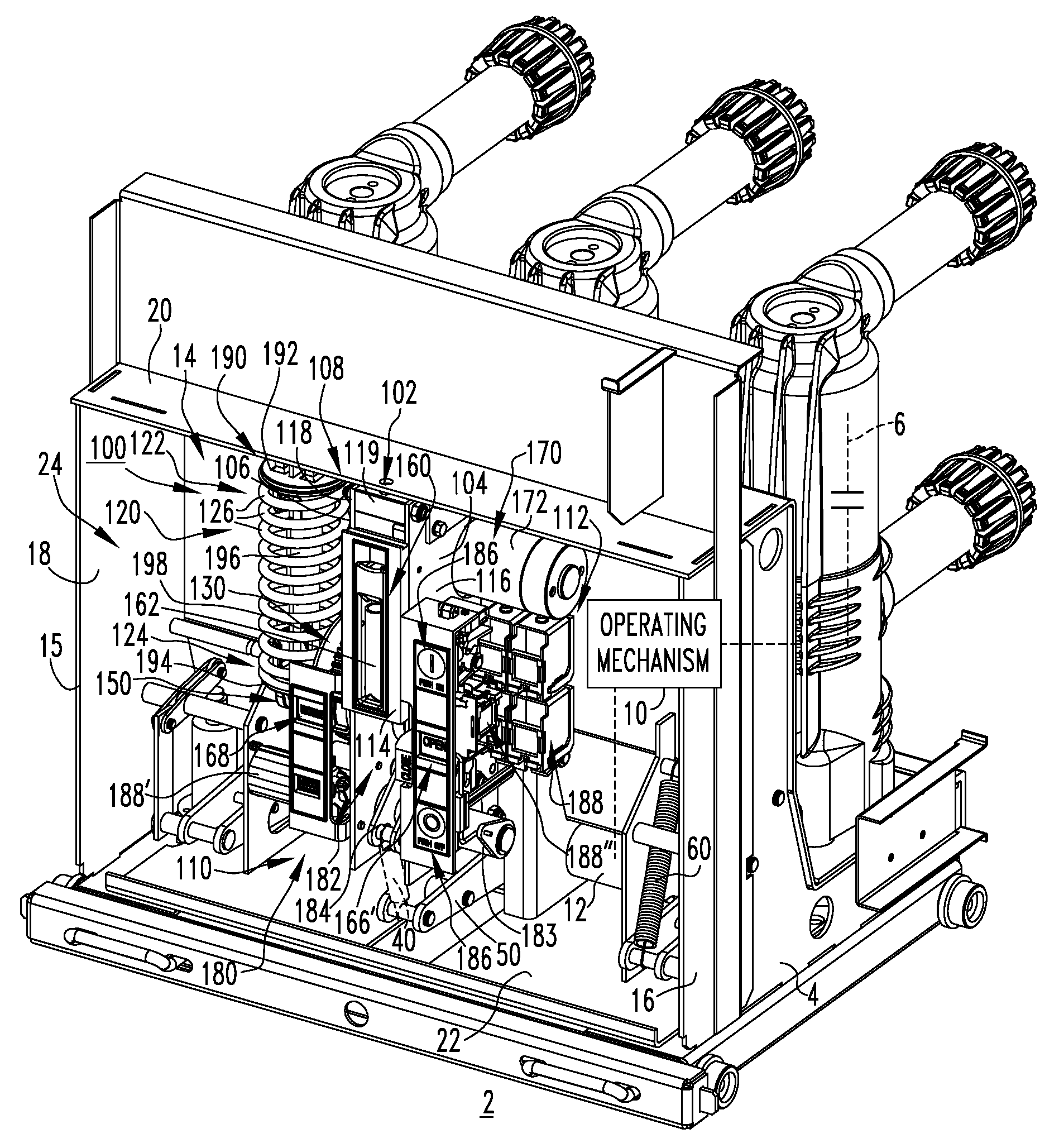
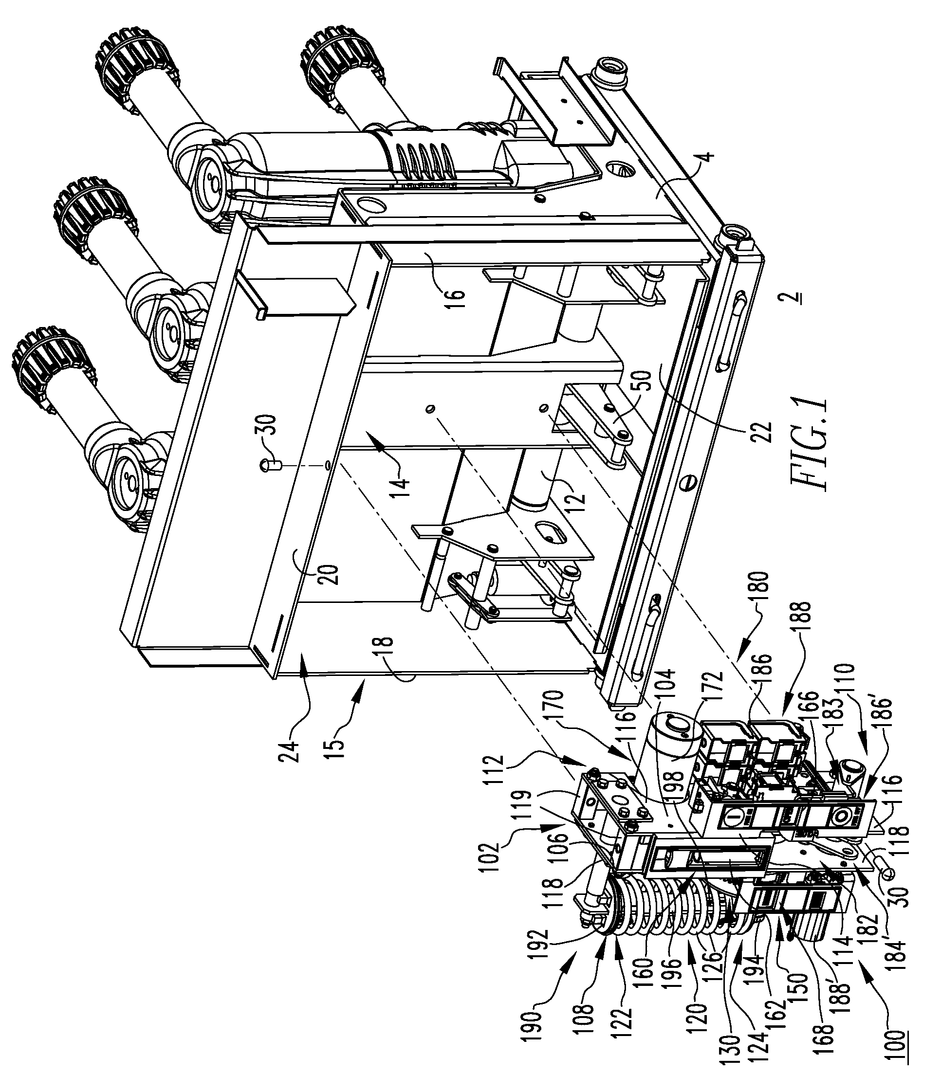
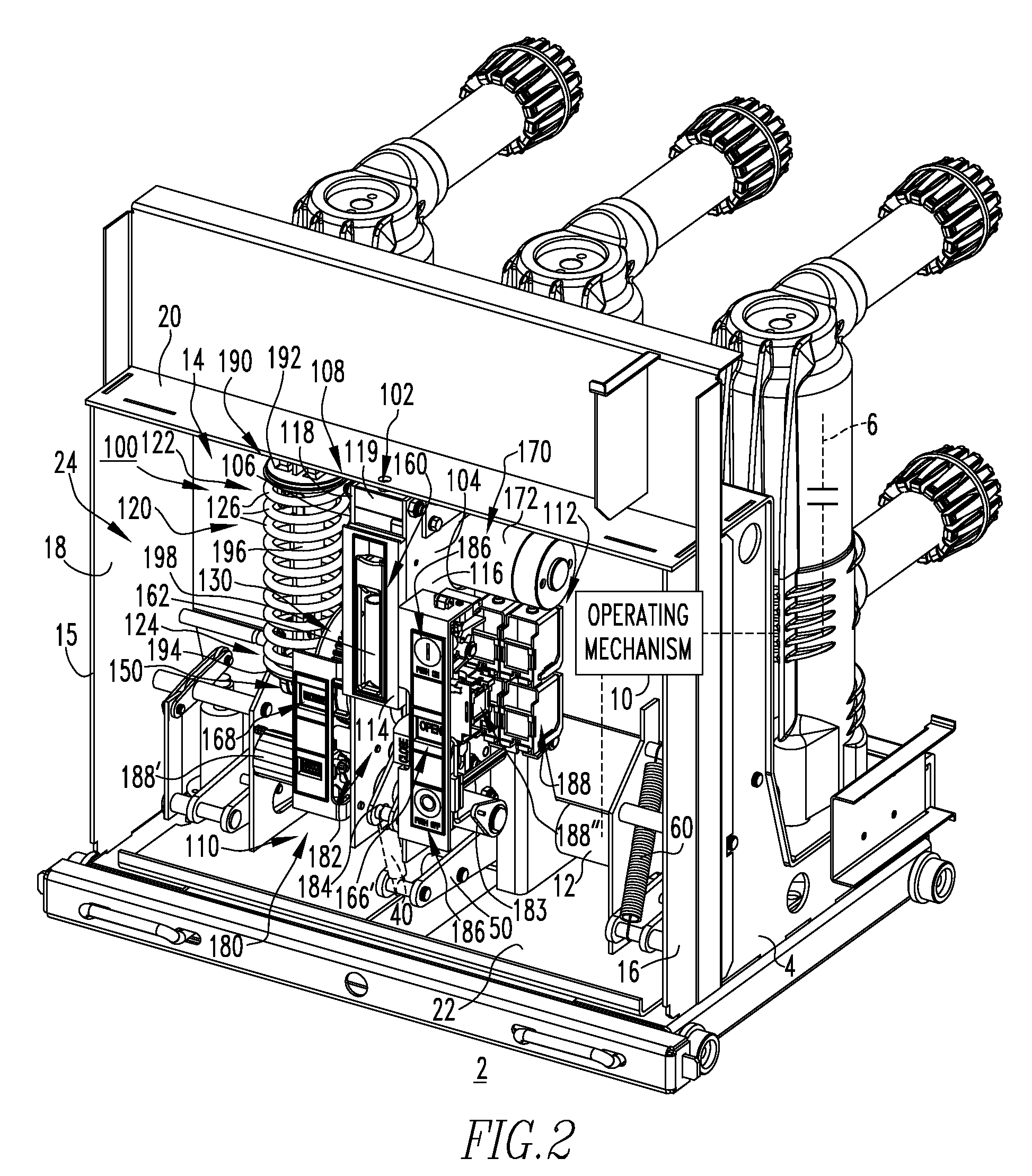
[0026]For purposes of illustration, embodiments of the invention will be described as applied to medium voltage circuit breakers, although it will become apparent that they could also be applied to a wide variety of electrical switching apparatus (e.g., without limitation, circuit switching devices and other circuit interrupters, such as contactors, motor starters, motor controllers and other load controllers) other than medium voltage circuit breakers and other than medium voltage electrical switching apparatus.

[0027]Directional phrases used herein, such as, for example, top, bottom, upper, lower, front, back, clockwise, counterclockwise and derivatives thereof, relate to the orientation of the elements shown in the drawings and are not limiting upon the claims unless expressly recited therein.

[0028]As employed herein, the phrase “self-contained” refers to the modular nature of the disclosed stored energy assembly, in which substantially all of the components (e.g., without limitat...


PUM


Abstract

A stored energy assembly is provided for an electrical switching apparatus, such as a circuit breaker. The stored energy assembly includes a mount removably coupled to the circuit breaker housing. A stored energy mechanism, such as a spring, is coupled to the mount and is movable among charged and discharged positions. An actuating element is cooperable with the gears of a gear assembly in order to move among first and second positions corresponding to the spring being disposed in the charged and discharged positions, respectively. A manual charging mechanism and an automatic charging mechanism are coupled to the gear assembly, and move the gears, in order to move the actuating element and charge the spring. The spring, the actuating element, the gear assembly, and the charging mechanisms are coupled to the mount, thereby forming a sub-assembly. The sub-assembly is removeably coupled to the circuit breaker housing.

Description

CROSS-REFERENCE TO RELATED APPLICATION[0001]This application is related to commonly assigned, concurrently filed: U.S. patent application Ser. No. 11 / 756,682, filed Jun. 1, 2007, entitled “ELECTRICAL SWITCHING APPARATUS, AND STORED ENERGY ASSEMBLY AND TIME DELAY MECHANISM THEREFOR”.BACKGROUND OF THE INVENTION[0002]1. Field of the Invention[0003]The invention relates generally to electrical switching apparatus and, more particularly, to stored energy assemblies for electrical switching apparatus, such as circuit breakers.[0004]2. Background Information[0005]Electrical switching apparatus, such as circuit breakers, provide protection for electrical systems from electrical fault conditions such as, for example, current overloads, short circuits, abnormal voltage and other fault conditions. Typically, circuit breakers include an operating mechanism which opens electrical contact assemblies to interrupt the flow of current through the conductors of an electrical system in response to suc...

Claims


Application Information

Patent Timeline
Patent Type & Authority Patents(United States)
IPC IPC(8): H01H5/00
CPCH01H3/3005H01H71/70H01H3/3031
Inventor CHEN, STEVEN Z.BENKE, JAMES J.EDMUNDS, ALAN K.PALMIERI, DANIEL E.BOTTEGAL, PAUL T.
Owner EATON INTELLIGENT POWER LTD
Why Eureka
Try Eureka