Supercharge Your Innovation With Domain-Expert AI Agents!

Illumination unit and liquid crystal display device including the same

a liquid crystal display and illumination unit technology, applied in lighting device details, lighting and heating apparatus, instruments, etc., can solve the problems of difficult to fabricate a thick light guide plate by injection molding, difficult to fabricate a light guide plate with bosses on the back surface, and increase the thickness of light guide plates, so as to facilitate the alignment of optical sheets, simplify the structure, and keep the alignment state

Inactive Publication Date: 2010-04-13
JAPAN DISPLAY CENTRAL CO LTD
View PDF2 Cites 8 Cited by
  • Summary
  • Abstract
  • Description
  • Claims
  • Application Information

AI Technical Summary

Benefits of technology

[0008]The present invention has been made in consideration of the above-described problems. An object of the invention is to provide an illumination unit which can easily align an optical sheet with a light guide plate and keep the alignment state, without the need for a separate member, and to provide a liquid crystal display device including this illumination unit. Another object of the invention is to provide an illumination unit which can simplify the structure for keeping the state in which an optical sheet and a light guide plate are aligned, and to provide a liquid crystal display device including this illumination unit.
[0011]The present invention can provide an illumination unit which can easily align an optical sheet with a light guide plate and keep the alignment state, without the need for a separate member, and to provide a liquid crystal display device including this illumination unit.
[0012]In addition, the present invention can provide an illumination unit which can simplify the structure for keeping the state in which an optical sheet and a light guide plate are aligned, and to provide a liquid crystal display device including this illumination unit.

Problems solved by technology

Thus, there is a tendency that the thickness of the light guide plate increases.
It is very difficult to fabricate a thick light guide plate by injection molding.
However, it is difficult to fabricate the light guide plate having bosses on the back surface, as disclosed in the above-described patent document, by a cutting process.
It is thus difficult to align the light guide plate, which is fabricated by the cutting process, with the optical sheet.
Besides, for example, a separate member, such as a double coated adhesive tape, is needed in order to fix the optical sheet to the light guide plate in the state in which the optical sheet is aligned with the light guide plate, leading to such problems as complexity in structure, complexity in a fabrication step for fixation, and an increase in manufacturing cost.

Method used


Image

  • Illumination unit and liquid crystal display device including the same
  • Illumination unit and liquid crystal display device including the same
  • Illumination unit and liquid crystal display device including the same

Examples


Embodiment Construction

[0021]An illumination unit according to an embodiment of the present invention and a liquid crystal display device including this illumination unit will now be described with reference to the accompanying drawings.

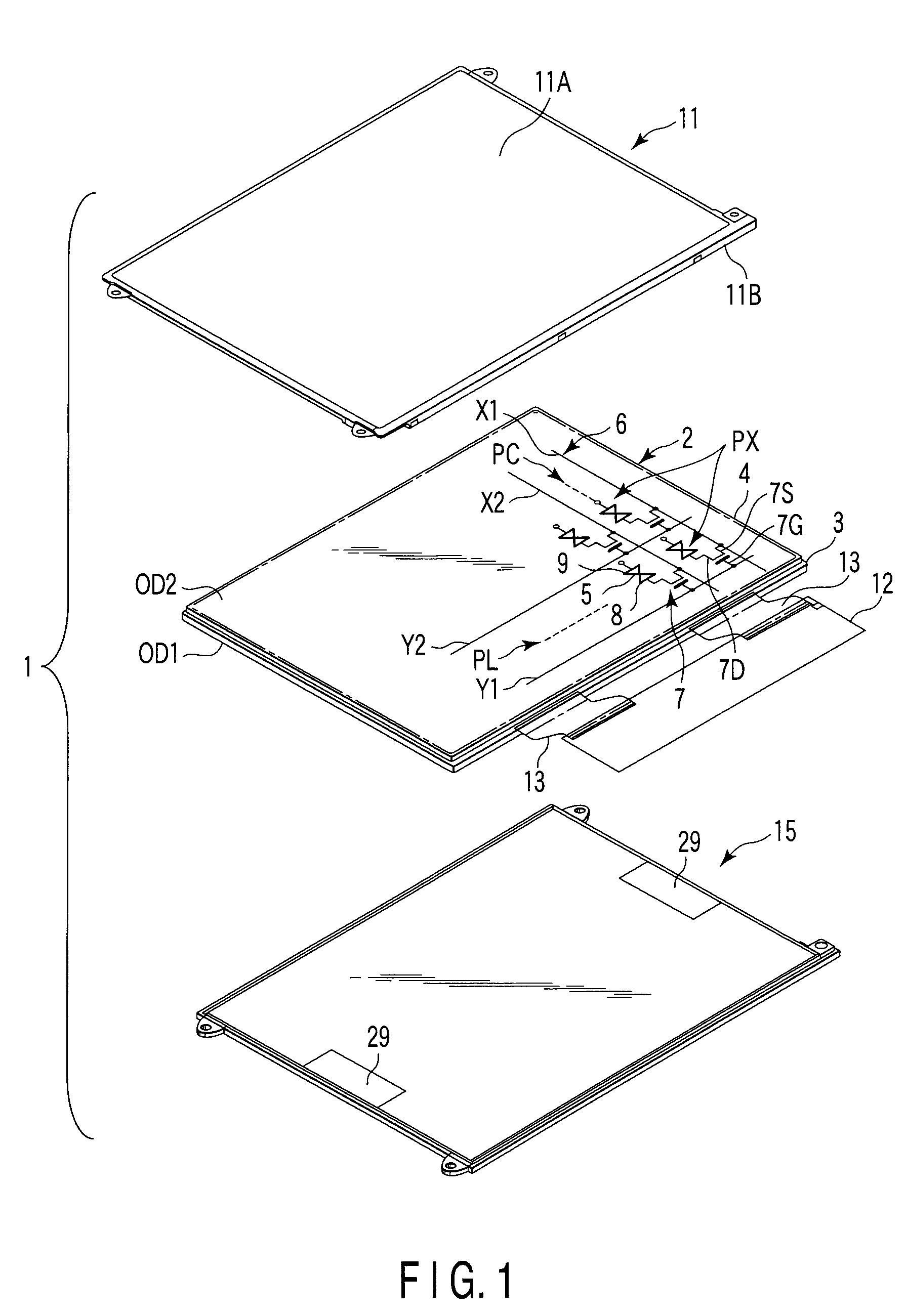
[0022]As is shown in FIG. 1, a liquid crystal display device 1 includes a substantially rectangular, planar transmissive liquid crystal display panel 2, and an illumination unit 15 which illuminates the liquid crystal display panel 2. The liquid crystal display panel 2 is configured such that a liquid crystal layer is interposed between a pair of substrates. Specifically, the liquid crystal display panel 2 includes a rectangular array substrate 3, a rectangular counter-substrate 4, and a liquid crystal layer 5 functioning as an optical modulation layer which is sealed between the pair of substrates via alignment films. The array substrate 3 and counter-substrate 4 are attached by a seal material. The liquid crystal display panel 2 includes a substantially rectangular activ...


PUM

PropertyMeasurementUnit
luminanceaaaaaaaaaa
thicknessaaaaaaaaaa
thickaaaaaaaaaa

Abstract

An illumination unit includes a light guide plate, and at least one optical sheet which is disposed on a major surface of the light guide plate. The optical sheet includes bent portions which are formed by bending portions of the optical sheet at a pair of opposed sides, and the light guide plate includes, at a pair of opposed end surfaces, recess portions in which the bent portions are inserted.

Description

CROSS-REFERENCE TO RELATED APPLICATIONS[0001]This application is based upon and claims the benefit of priority from prior Japanese Patent Application No. 2007-149444, filed Jun. 5, 2007, the entire contents of which are incorporated herein by reference.BACKGROUND OF THE INVENTION[0002]1. Field of the Invention[0003]The present invention relates generally to an illumination unit and a liquid crystal display device including the illumination unit, and more particularly to a structure for aligning an optical sheet of an illumination unit with a light guide plate and keeping the alignment state.[0004]2. Description of the Related Art[0005]A technique for fixing an optical sheet to a light guide plate has been proposed (see, e.g. Jpn. Pat. Appln. KOKAI Publication No. 2006-201210). According to this patent document, bosses (projections), which are integrally formed on a back surface of a light guide plate, are passed through through-holes of a reflection sheet, and inserted in boss-recei...

Claims


Application Information

Patent Timeline
Patent Type & Authority Patents(United States)
IPC IPC(8): G02F1/1335
CPCF21V7/05G02B6/0088G02F1/133615G02F2001/133322G02F1/133606G02F1/133322
Inventor SHIMIZU, MAKOTO
Owner JAPAN DISPLAY CENTRAL CO LTD
Features
  • R&D
  • Intellectual Property
  • Life Sciences
  • Materials
  • Tech Scout
  • Unparalleled Data Quality
  • Higher Quality Content
  • 60% Fewer Hallucinations
Learn More