System and method for efficient analysis of point-to-point delay constraints in static timing

a point-to-point delay and static timing technology, applied in the field of design automation, can solve the problems of high cost of incremental execution of path tracing methods, inability to easily use, and large memory and runtime overhead of applying such point-to-point assertions, so as to reduce the number of instances

Inactive Publication Date: 2010-04-13
GLOBALFOUNDRIES INC
View PDF24 Cites 19 Cited by
  • Summary
  • Abstract
  • Description
  • Claims
  • Application Information

AI Technical Summary

Benefits of technology

[0019]It is another object of the invention to provide a process for evaluating bounds to reduce the number of instances in which more detailed path tracing and / or additional tags are required to determine whether particular point-to-point constraints have been satisfied.
[0022]In one aspect of the present invention there is provided a method that enables categorizing point-to-point delay constraints as definitely passing or definitely failing, by use of both conservative and optimistic bounds which can be applied in situ. For other cases that cannot definitely be categorized as passing or failing, prior art methods may be resorted to in order to make a concrete determination. The inventive method reduces the number of instances in which exponential path tracing and / or the use of additional tags are required, when compared to prior existing methods.

Problems solved by technology

Due to its exponential complexity, the path tracing method is expensive to execute incrementally and is therefore not easily usable by automated optimization methods which make numerous changes to the timing graph in order to correct for timing, power, and / or noise violations.
Even when used non-incrementally, application of such point-to-point assertions may be highly time consuming due to the need to identify all possible paths between specified from and to points.
Methods which use additional tags may avoid the need for explicit path tracing and therefore can be incremental; however, these techniques typically incur a large memory and runtime overhead due to the need to introduce additional tagged timing values in the entire fan-out cone of the “from” node of every such point-to-point assertion, or at all points in the intersections of the fan-out cone of the “from” node and the fan-in cone of the “to” node of the point-to-point assertion.
For each such tag, a unique version of AT / RAT / slew values is computed and stored, significantly increasing the memory overhead.
Furthermore, since each tag has a different slew value, and delay and slew calculation for an edge in a timing graph generally depend on the slew at the source of that edge, a unique corresponding delay and sink slew calculation is required, increasing the runtime overhead as well.

Method used


Image

  • System and method for efficient analysis of point-to-point delay constraints in static timing
  • System and method for efficient analysis of point-to-point delay constraints in static timing
  • System and method for efficient analysis of point-to-point delay constraints in static timing

Examples


Embodiment Construction

[0032]The present invention and various features, aspects and advantageous details thereof are explained more fully with reference to the non-limiting embodiments that are illustrated in the accompanying drawings and detailed in the following description. It should be noted that the features illustrated in the drawings are not necessarily drawn to scale. Descriptions of well-known components and processing techniques are omitted so as to not unnecessarily obscure the present invention in detail.

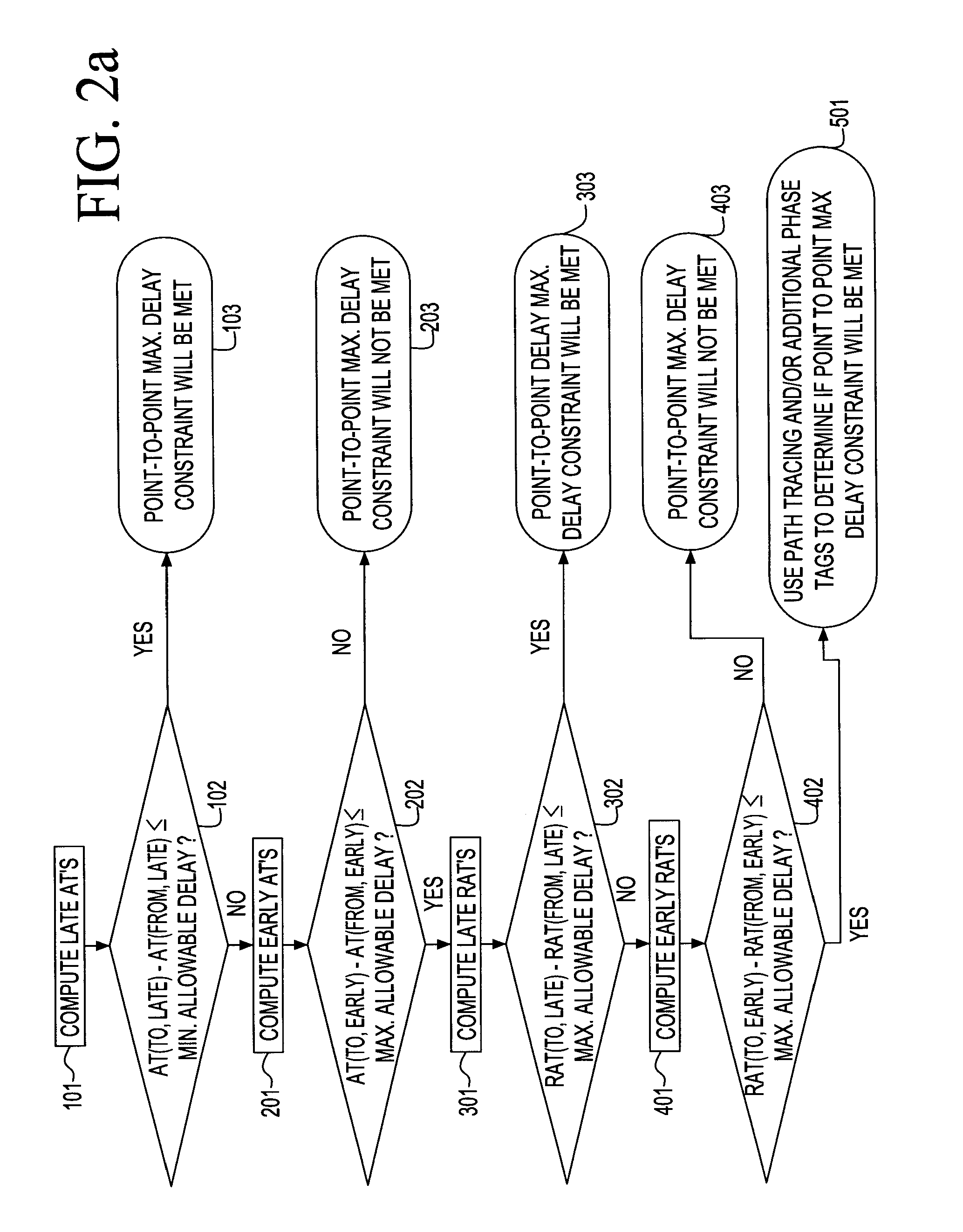
[0033]FIGS. 2a and 2b are flowcharts illustrating the inventive method as applied to maximum and minimum point to point delay constraints, respectively. In order to further appreciate the present methodology and details thereof, initially several simple illustrative examples will be provided in conjunction with the various steps of the present invention as embodied by the two flowcharts.

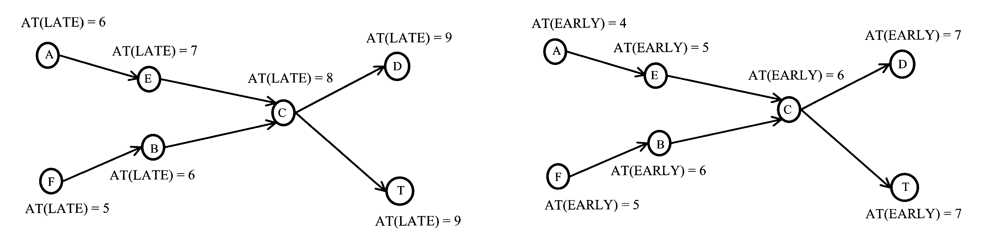
[0034]Referring to FIG. 3, an illustrative circuit is shown comprising two primary input pins A and F, two ...


PUM


Abstract

A method and a system for conducting a static timing analysis on a circuit having a plurality of point-to-point delay constraints between two points of the circuit, in which two conservative and two optimistic user defined tests are derived for all types of the point-to-point delay constraints. The method shows that when a conservative test is performed without introducing any special tags, then it is found that the point-to-point constraint is satisfied. On the other hand, when the optimistic test fails without any special tags, it is determined that the point-to-point constraint is bound to fail if special tags are introduced, in which case, they are to be introduced only when an exact slack is desired. Finally, for anything in between, a real analysis with special tags or path tracing is required. Based on the topology of the graph, arrival time based tests may be tighter in some situations, while the required arrival time based tests, may be tighter in others.

Description

FIELD OF THE INVENTION[0001]The present invention generally relates to the field of Design Automation, and more particularly, to a system and method for analyzing point-to-point delay constraints in static timing analysis.BACKGROUND OF THE INVENTION[0002]The goal of static timing analysis (STA) is to determine the latest and earliest possible switching times of various signals within a digital circuit. STA may generally be performed at the transistor level or at the gate level, using pre-characterized library elements, or at higher levels of abstraction, for complex hierarchical chips.[0003]STA algorithms operate by first levelizing the logic structure, and breaking any loops in order to create a directed acyclic graph (timing graph). Modern designs can often contain millions of placeable objects, with corresponding timing graphs having millions, if not tens of millions of nodes. For each node, a corresponding arrival time, transition rate (slew), and required arrival time are compu...

Claims


Application Information

Patent Timeline
Patent Type & Authority Patents(United States)
IPC IPC(8): G06F17/50G06F9/45
CPCG06F17/5031G06F30/3312
Inventor KALAFALA, KERIMBANERJI, REVANTAHATHAWAY, DAVID J.SHERIDAN, JESSICAVISWESWARIAH, CHANDRAMOULI
Owner GLOBALFOUNDRIES INC
Why Eureka
Try Eureka