Modified Christmas tree components and associated methods for using coiled tubing in a well

a technology of coiled tubing and components, which is applied in the direction of drilling pipes, wellbore/well accessories, sealing/packing, etc., can solve the problems of increasing costs, needing to modify surrounding components, and requiring additional time for a crew to complete work

Active Publication Date: 2010-04-20
BAKER HUGHES HLDG LLC
View PDF9 Cites 62 Cited by
  • Summary
  • Abstract
  • Description
  • Claims
  • Application Information

AI Technical Summary

Benefits of technology

[0029]In one embodiment, an end of a new valve housing having the new upper shut-off valve is connected to the existing valve housing of the lower shut-off valve. Then, the flow tee is connected to another end of the new valve housing, and the gate valves are connected to the flow tee. In another embodiment, one end of a new integral housing is connected to the existing valve housing of the lower shut-off valve. The new integral housing has the new upper shut-off valve integrally formed with a flow tee. The gate valves are then connected to the flow tee of the new integral housing. When connecting the one or more modified components to the lower shut-off valve, the existing distance between a flow line elevation and a production elevation of the Christmas tree is maintained so that additional modifications (e.g., modifying the elevation of flowlines) are not required.

Problems solved by technology

The need to modify surrounding components can increase costs and may require additional time for a crew to complete the work.
The Y-body tree 50 requires that the body 60 be intricately constructed and integrally formed, which can increase costs.
Furthermore, the coil tubing bore 70 may be prone to damage because it projects outwardly and upwardly from the majority of the Y-body tree 50.

Method used


Image

  • Modified Christmas tree components and associated methods for using coiled tubing in a well
  • Modified Christmas tree components and associated methods for using coiled tubing in a well
  • Modified Christmas tree components and associated methods for using coiled tubing in a well

Examples


Embodiment Construction

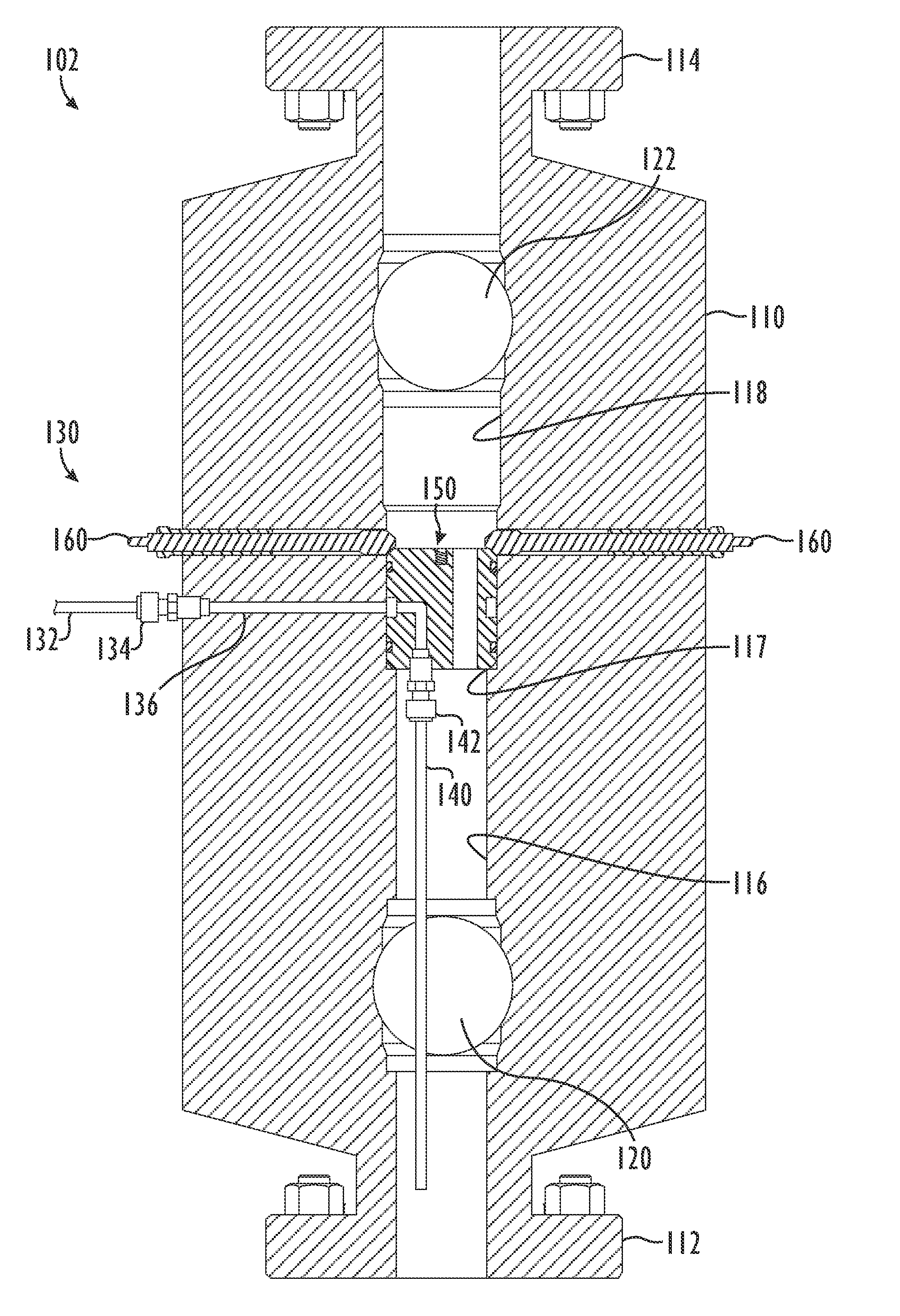
[0033]Referring to FIG. 3A, an embodiment of a Christmas tree arrangement 100 according to certain teachings of the present disclosure is illustrated in an elevational view. The Christmas tree arrangement 100 has a lower portion 102, an intermediate portion 104, and an upper portion 106. The lower portion 102 includes a tubing head adapter 16 attached to a tubing head 12, as are commonly used. The intermediate portion 104 includes an integral body 110 housing a lower shut-off valve 120 and an upper shut-off valve 122. The upper portion 106 includes a flow tee 22 and includes gate valves 24 and 26 and a top cap 14 that attach to the flow tee 22 in a conventional manner.

[0034]The integral body 110 of the intermediate portion 104 has a lower flange 112 that couples to the tubing head adapter 16. The integral body 110 also has an upper flange 114 onto which the flow tee 22 attaches. The axial dimension h, of the integral body 110 is configured so as to substantially maintain the axial d...


PUM


Abstract

A Christmas tree is used between production tubing elevation and flow line elevation. The tree has a lower portion, an intermediate portion, and an upper portion. The intermediate portion is positioned between the production tubing elevation and the flow line elevation and has an axial dimension configured to substantially maintain the axial dimension between the elevations. The intermediate portion has first and second shut-off valves for closing fluid communication of the axial bore. A hanger is positioned in the axial bore of the intermediate portion between the first and second shut-off valves. The hanger defines a bore and a port. The port communicates a side of the hanger with the lower end of the hanger. The coil tubing attaches to the port at the lower end of the hanger, and the port at the side of the hanger communicates with the feed line of the intermediate portion.

Description

FIELD OF THE DISCLOSURE[0001]The subject matter of the present disclosure generally relates to modified Christmas tree components and associated methods for using coiled tubing in oil and gas wells.BACKGROUND OF THE DISCLOSURE[0002]Referring to FIG. 1A, a Christmas tree 10 according to the prior art is illustrated in an elevational view. The Christmas tree 10 is attached atop conventional components of a wellhead known in the art. The tree 10 includes a tubing head 12, a tubing head adapter 16, a lower master gate valve 18, an upper master gate valve 20, and a flow tee 22. The flow tee 22 has a flow line gate valve 24 and a kill line gate valve 26. The gate valves 24 and 26 connect to additional components (e.g., piping) situated at a flow line elevation FE. The flow line elevation FE is measured from a production elevation, which can be measured from the top of the tubing head adapter 16 (e.g., production elevation PE) or measured from the bottom of the tubing head 12 (e.g., altern...

Claims


Application Information

Patent Timeline
Patent Type & Authority Patents(United States)
IPC IPC(8): E21B19/02
CPCE21B33/068E21B33/03
Inventor BOLDING, JEFFHILL, JR., THOMAS G.
Owner BAKER HUGHES HLDG LLC
Why Eureka
Try Eureka