Control circuit and method for multi-mode buck-boost switching regulator

a control circuit and regulator technology, applied in the direction of dc-dc conversion, climate sustainability, power conversion systems, etc., can solve the problems of difficult control of process, inability to quickly and finely adjust, and low efficiency, so as to improve the efficiency of the regulator and facilitate design.

Inactive Publication Date: 2010-04-20
FARADAY TECH CORP
View PDF5 Cites 16 Cited by
  • Summary
  • Abstract
  • Description
  • Claims
  • Application Information

AI Technical Summary

Benefits of technology

[0010]Accordingly, the present invention provides a control circuit of a multi-mode buck-boost switching regulator, which has an advantage that it is easy to be designed, and at most only two switches are required to be driven in each working cycle, without operations of all the switches, so as to improve the efficiency of the regulator.
[0011]The present invention also provides a method of controlling a multi-mode buck-boost switching regulator, which has an advantage that whenever the output voltage of the regulator changes, the duty cycle of the switch is changed accordingly, which is sensitively and finely adjusted according to the load change.
[0021]In the above control circuit and the controlling method of the multi-mode buck-boost switching regulator, in a single cycle of the first triangle wave and the second triangle wave, at most two switches perform switching operations, so the efficiency of the regulator is relatively high, which solves the problem of U.S. Pat. No. 6,166,527 that all the four switches in one working cycle perform switching operations in the buck-boost mode. Meanwhile, in the buck-boost mode, as the level of the control signal changes, the duty cycles of the switches are changed accordingly. Therefore, the multi-mode buck-boost switching regulator is relatively sensitive, thus solving the problem of the U.S. Pat. No. 6,984,967. In the present invention, the advantages of the two conventional art are combined, and the two disadvantages of the conventional art are avoided. The design and the logic rule of the present invention are very simple. It is easy to use simple digital elements such as comparators and logic gates to form the logic circuit of the present invention for controlling the switch, which does not require the complicated analog circuits as that of the U.S. Pat. No. 6,984,967.

Problems solved by technology

The disadvantage is that, in the buck-boost mode, in a single working cycle, that is, in a signal cycle of the triangle wave control signals VX and VY, all the four switches A, B, C, and D perform the switching operation of ON and OFF.
So the efficiency is very low.
On the other hand, the disadvantage lies in that, the circuit is complicated, and because a lot of reference voltages are required to be generated, the process is difficult to control.
Another disadvantage is that, the time point for the switching of the switch is determined according to the comparison between the triangle wave control signal 409 and the precise reference voltage signals 407, so the duty cycle of the switch is fixed, and the control signal VCL of the comparator 403 is not used to determine the time point for the switching of the switch, so it cannot be quickly and finely adjusted according to the fluctuation of the load 214, and thus, only several fixed operation modes exist, which does not meet the requirement of sensitivity.

Method used


Image

  • Control circuit and method for multi-mode buck-boost switching regulator
  • Control circuit and method for multi-mode buck-boost switching regulator
  • Control circuit and method for multi-mode buck-boost switching regulator

Examples


Embodiment Construction

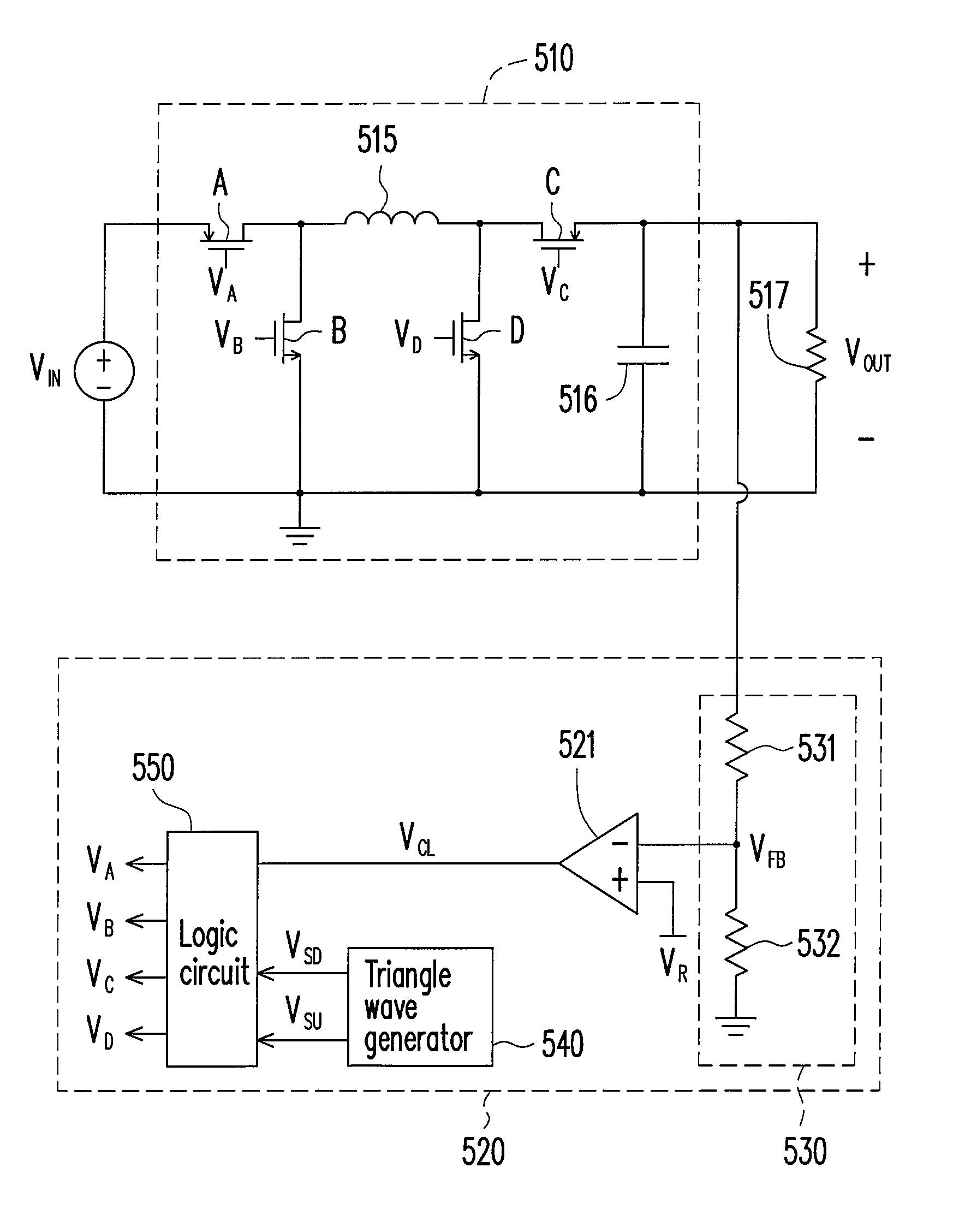
[0032]FIG. 5 shows a multi-mode buck-boost switching regulator 510 and a control circuit 520 thereof of an embodiment of the present invention. The multi-mode buck-boost switching regulator 510 includes switches A, B, C, and D, an inductor 515, and an output capacitor 516. The switch A receives an input voltage VIN, the switch B is coupled between the switch A and the ground terminal, the inductor 515 is coupled to the switch A and the switch B, the switch D is coupled between the inductor 515 and the ground terminal, the switch C is coupled to the inductor 515 and the switch D, and the output capacitor 516 is coupled between the switch C and the ground terminal, which provides an output voltage VOUT of the multi-mode buck-boost switching regulator 510 to the load 517.

[0033]The control circuit 520 includes a comparator 521, a triangle wave generator 540, a logic circuit 550, and a voltage-dividing circuit 530. The comparator 521 outputs a control signal VCL according to an error bet...


PUM


Abstract

A control circuit of a multi-mode buck-boost switching regulator and a method thereof are provided. The control circuit imposes ON / OFF timing sequences on switches according to the relationship between two controlling triangle waves and the load fluctuation. In each working cycle of each mode of the regulator, at most two switches perform switching operations. The control circuit is simple to design, which only includes simple digital elements, such as comparators, logic gates etc., instead of complicated analog circuits.

Description

BACKGROUND OF THE INVENTION[0001]1. Field of the Invention[0002]The present invention relates to a multi-mode buck-boost switching regulator, and more particularly, to a control circuit and a method for multi-mode buck-boost switching regulator.[0003]2. Description of Related Art[0004]Referring to FIG. 1, FIG. 1 is an architecture view of a conventional multi-mode buck-boost switching regulator and a control circuit thereof. The multi-mode switching means three operations, including boost mode, buck mode, and buck-boost mode. As the name implies, the boost mode indicates that in a certain working cycle, the input voltage VIN is boosted to obtain another voltage output. The buck mode indicates that in a certain working cycle, the input voltage VIN is bucked to obtain another voltage output. The buck-boost mode indicates that in a certain working cycle, the input voltage VIN is first boosted and then bucked, or it is first bucked and then boosted to obtain another voltage output. The ...

Claims


Application Information

Patent Timeline
Patent Type & Authority Patents(United States)
IPC IPC(8): G05F1/24G05F1/575
CPCH02M3/157H02M3/1588H02M3/1582Y02B70/1466Y02B70/10
Inventor CHEN, KE-HORNGLIN, YUNG-HSINYU, CHENG-TA
Owner FARADAY TECH CORP
Why Eureka
Try Eureka