Apparatus and method for use in a well bore

a technology for wells and apparatuses, applied in the direction of wells/well accessories, fluid removal, sealing/packing, etc., can solve the problems of loss of contact between blades and walls, prone to deviation of plugs from central axes, and loss of the required sealing function

Active Publication Date: 2010-04-27
TERCEL IP
View PDF9 Cites 8 Cited by
  • Summary
  • Abstract
  • Description
  • Claims
  • Application Information

AI Technical Summary

Benefits of technology

[0029]In an alternative embodiment, the lower element comprises the ball seat. More preferably the lower element is located in the first bore. In this way, the second operation of the tool is to block the restric...

Problems solved by technology

A disadvantage of these plugs is that, in making the blades sufficiently flexible to fold back, the plug is prone to deviate from the central axis as it passes through the well bore above the restriction.
This deviation can cause loss of contact between the blades and the wall, thus losing the required sealing function.
Further the deviation can cause the nose to strike any ledge at the top of the restriction which result...

Method used


Image

  • Apparatus and method for use in a well bore
  • Apparatus and method for use in a well bore
  • Apparatus and method for use in a well bore

Examples


Embodiment Construction

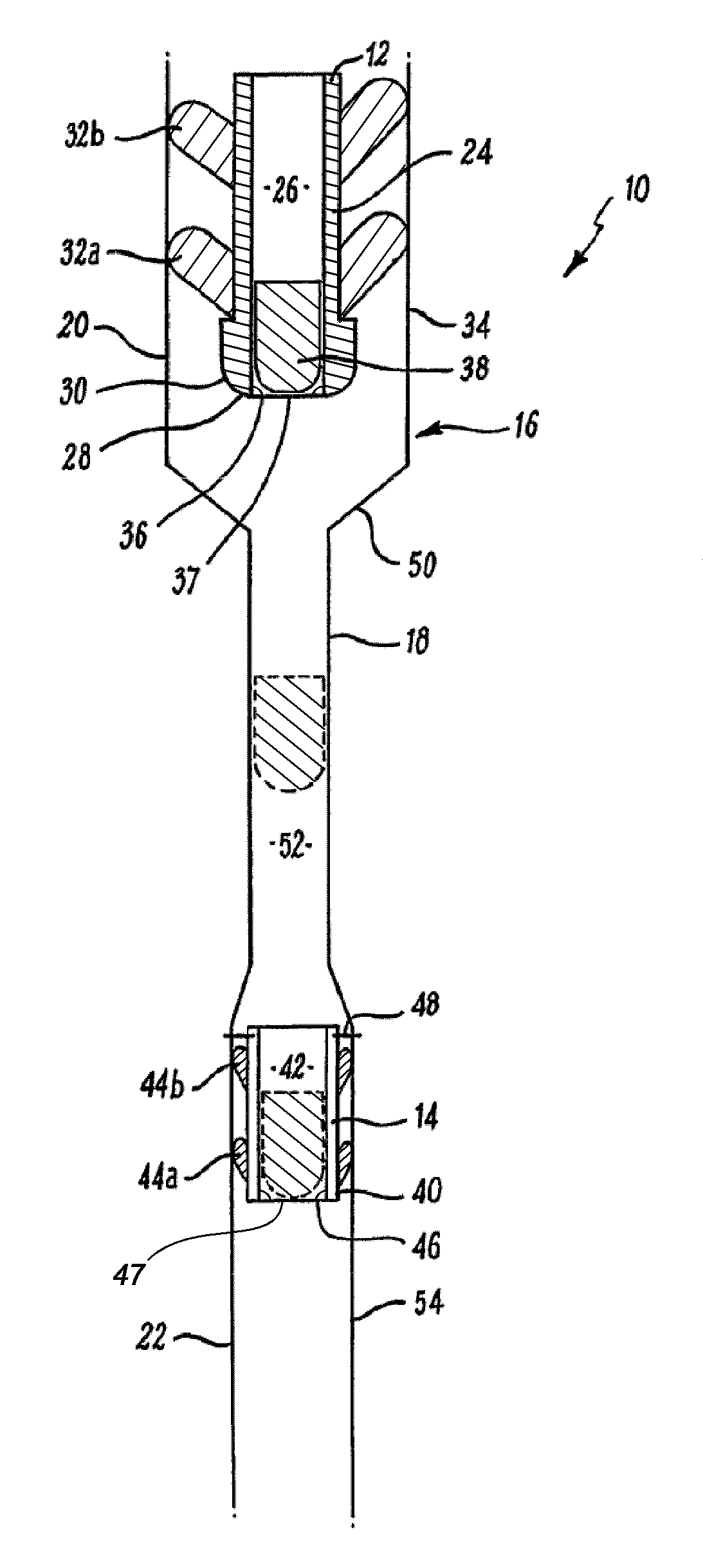
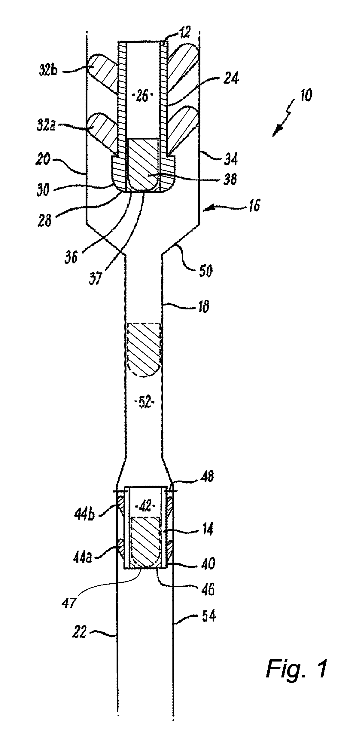
[0056]Reference is initially made to FIG. 1 of the drawings which illustrates apparatus, generally indicated by reference numeral 10, according to an embodiment of the present invention. Apparatus 10 comprises an upper element being an upper wiper plug 12 and a lower element, being a lower wiper plug 14. The well bore 16 has a narrowed bore or restriction 18 lying between upper 20 and lower 22 portions with diameter greater than that of the restriction 18. The upper wiper plug 12 is sized to pass through the upper portion 20 and the lower wiper plug 14 is initially located in the lower portion 22 and sized to pass therethrough.

[0057]The restriction 18 may be a result of the insertion of liner, production tubing or other narrow bore tubing used in the drilling and / or completion of a well bore. Alternatively the restriction 18 any exist in the through bore of the deployment string, work string or even a running tool, depending on the space requirement of the tools mounted thereon. The...


PUM


Abstract

Apparatus for use above and below a restriction in a well bore and a method of operation is described. The apparatus comprises an upper element, such as a wiper, operable in the well bore above the restriction and a lower element, which may be a lower wiper, operable in the well bore below the restriction. A drop ball sized to pass through the restriction is released from the upper element and thereby passes through the restriction to operate the lower element. In one embodiment, the apparatus is incorporated into a running tool, which may be used to hang liners by dimple forming.

Description

BACKGROUND OF THE INVENTION[0001]The present invention relates to the operation of tools above and below restrictions in a well bore and in particular, though not exclusively, to a running tool with wiper plugs used to cement casing or liner in a well bore.[0002]In operating tools in a well bore, it is common to have to work around restrictions in the diameter of a well bore. Such restrictions may be in the diameter of casing, liner, production tubing or deployment string. Restrictions may also exist in the through bore of the work string or deployment string depending on the space requirement of the tools mounted thereon. The restrictions may be a reduction in diameter of the bore, or a convoluted path in the bore. Thus there is a need to design tools which can operate effectively above and below such restrictions.[0003]In the field of cementing in well bores, plugs are used to separate fluids pumped through the well bore. These plugs typically comprise an elongate body terminating...

Claims


Application Information

Patent Timeline
IPC IPC(8): E21B33/00E21B33/08E21B33/16
CPCE21B33/16
Inventor WARDLEY, MICHAEL
Owner TERCEL IP
Why Eureka
Try Eureka