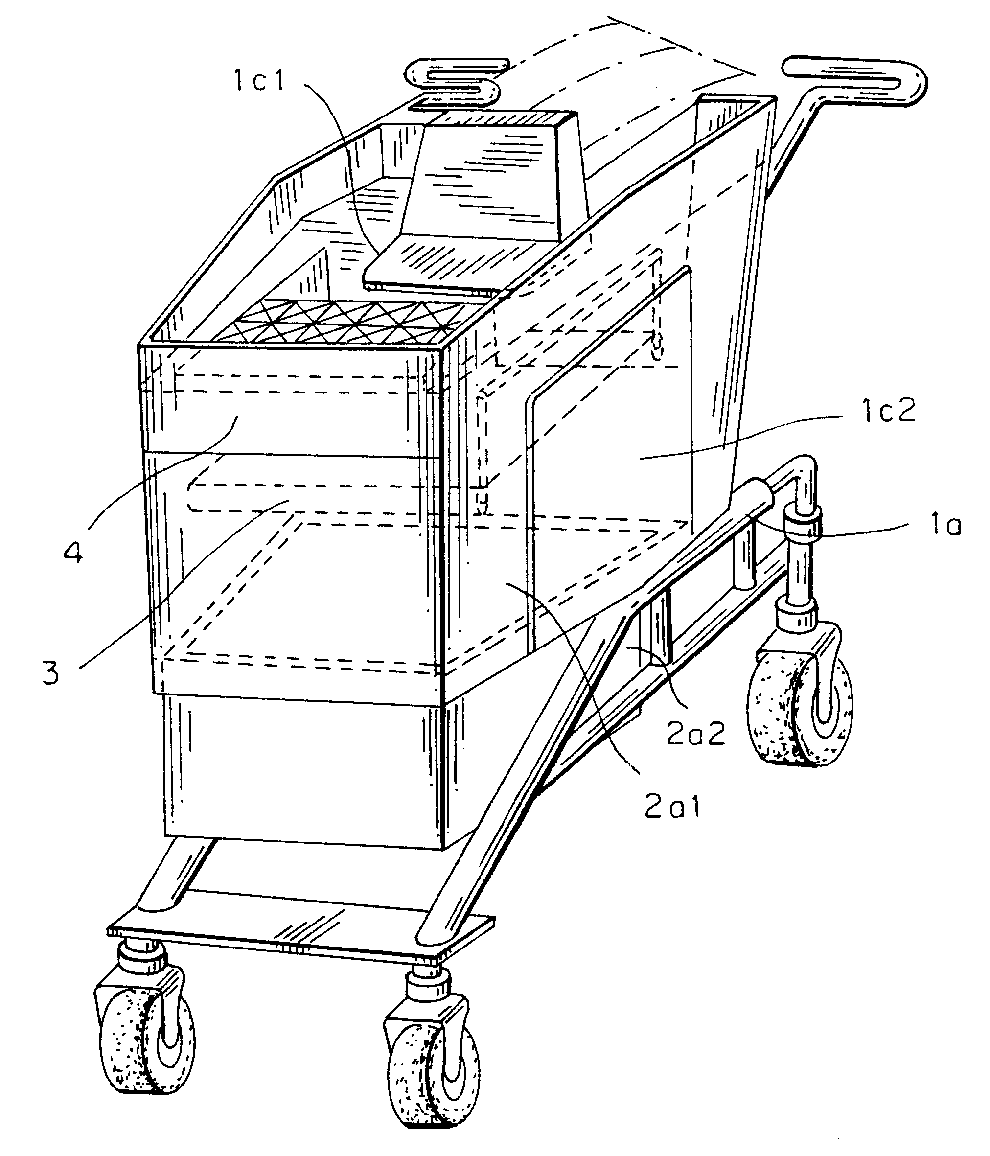
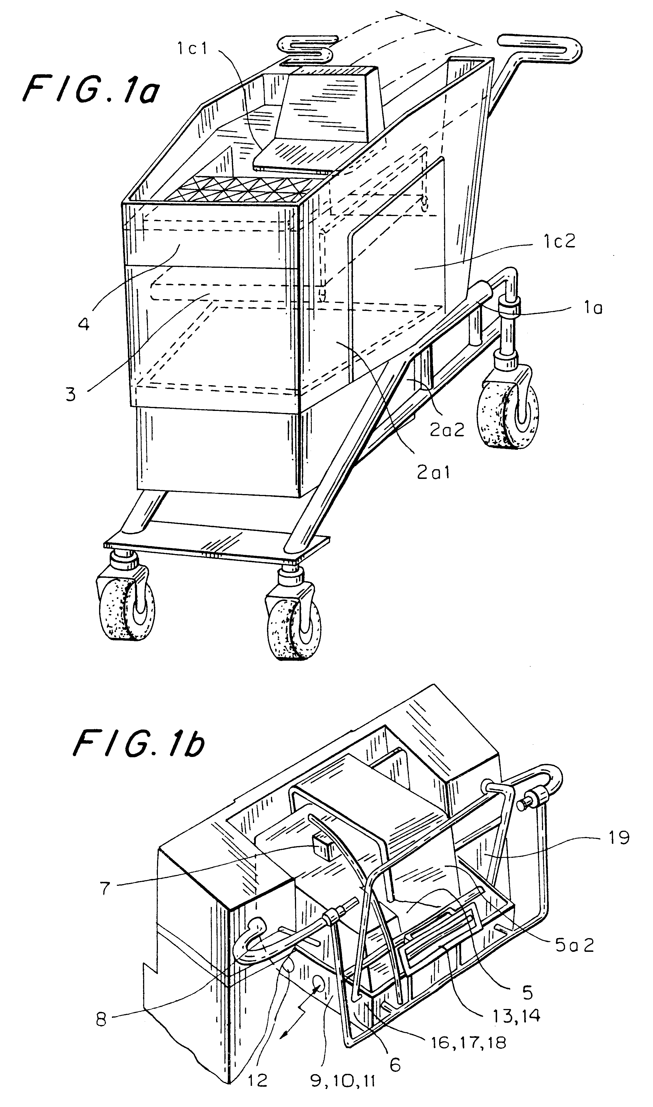
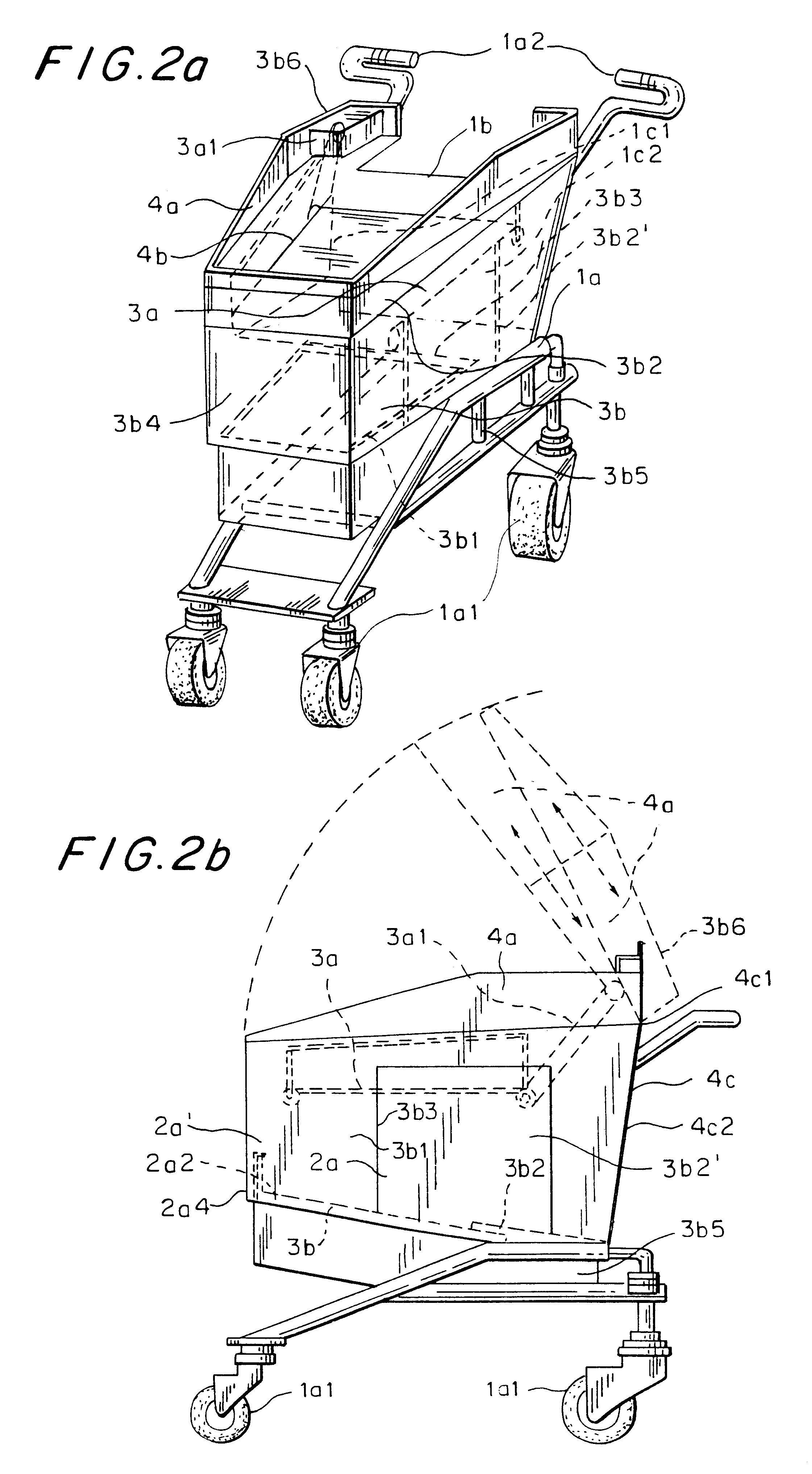
The invention shown in the drawings, as per TABLE 1, FIGS. 1a, 1b, comprises in general the movable closed 1a1 grocery container 1 (mechanical cart), connected through an electromechanical 15 latching unlatching system 19 to the unit for their insertion 5; the container comprises a system 2 for the variation (increase) of its internal capacity constituted by the base 2a conveniently movable downward; it comprises a closing / opening system 4 constituted by a pair of panels 4a conveniently connected to the structure and openable, and it comprises 20 a distribution / attenuation system 3 (product collector), constituted by the fixed plane which can conveniently be eliminated and by the movable platform 3b conveniently: the insertion unit comprises a product inlet compartment Sa1 accessible through the double doors 5a2, Sa8 which stands on the weighing plate 8a of the related system 8, whilst 25 on the upper part and along the vertical to the wall extends the automatic system 7 for reading bar codes (UPC / EAN) culminating in the related device 7a; under the base, within the closed compartment 5c, it comprises the computerized unit 6 (shopping-computer), with related operating software 16, process control firmware 17, communication software 18 and the other electronic parts: system for the exchange of 5 commands / messages in general via ether directionally 9, omnidirectionally 10, via cable 11, commercial message emission system 12, market research 13, pastimes 14, autonomous power supply 15; extremely visible are the command input unit 6f (keyboard) and the output unit (display) 6n, which together with software 16,17718 and data base 6d characterize the SHOPPING-COMPUTER of new design to manage shopping problems, in the context of the cart; lastly it comprises, to the front the grip 5d, to maneuver the cart; in particular the mechanical cart 1, as per TABLE 2FIG. 2a comprises a base structure 1a and movable structure 1a1 bearing the closed compartment 1c2 of the internal products, surmounted by a top external one 1c1; it comprises an expansion system constituted by appropriate closures and the various sides (2a1) towards the inner walls of the main platform (3b) appropriately connected 2a3 to the vertical guides by elastic devices 2a3 such as to extend themselves automatically (internal capacity expansion) under the load of the products inserted; lastly it comprises the outer wall 2a2, which integrates the wall missing from the basket, during expansion; the system conveniently connected 3b3 to the secondary one fastened with elastic devices 3b4 to the vertical guides 3b:, and actuated by appropriate electrical devices 3b5 or other means; it comprises a longitudinal surface (product dispenser) able to be wound around the pairs of rollers 3a2 (under tension) fixed to the load bearing structure and through gears, belts, levers 3a1 to the manual control 3a2: from its side view in FIG. 2b the platform comprises the main module 3b1; moreover from the top view in TABLE 3--FIG. 3a it is seen to comprise a diverging recess on the upper part such as perfectly to fit the product insertion unit 5, at the moment of latching with the cart plus computerized unit set becoming a single compact body; it comprises the upper basket (external products) 1c1; from the drive side view of FIG. 3b, at the base one notes the motion devices 1a1, it comprises a pair of panels 4c2 to integrate the front one 4a, hinged to the load 10 bearing structure and revolving inward and upward and appropriately connected thereto and able to slide; it comprises a window which will correspond, to the outlet of the product insertion unit (when applied); a pair of appropriate devices 19a for latching and 19e for electrical contact towards the on-board system, in line with those of the grip to the product 15 insertion unit; the system for opening (product removal) as shown in FIG. 3c comprises a single structure constituted by a pair of panels 4a interconnected, able to slide, to fit within each other and hinged 4c1 to the cart itself, revolving upwards in a rest position, such as to free the entire mouth of the cart, for removal of the products (after removing the products from the upper external compartment 1c1); conversely, in the closed position when the insertion unit is applied, a series of devices assures both the unfolding 4b of the panels (cascade fitting), and a latching 19a at an angle such as to ensure the closure of the internal space (otherwise there is no hitching to the insertion unit); as shown in 25FIG. 3d, it comprises the closure structure 4a in rest position, the platform 3b resting on the cart base, as well as the sliding base basket 2a, in line with the cart, whilst the front panel 4c rotate upward, thanks to the thrust of the front cart, as well as the supplementary panels 4c2 in recessed position as an effect of the elastic devices: in particular the computerized product insertion unit 5, as shown in TABLE 4--FIG. 54a comprises the product inlet compartment Sa1 whereto access is gained through the upper door 5a2 sliding on appropriate guides Sa4, upon manual command 2a2 and exit one 5a8 connected through appropriate gears, belts, levers 5a14 to the manual control 5a15e at the same time (sole control) connected to the ejection system 5b; the 10 alternative opening of the doors 5a2, Sa8 occurs with the aid of the contact sensors 5a5, Sa11 and of the block 5a6, Sa12; it comprises the automatic system 7 for optically scanning bar codes constituted by the optical device 7a of the UPC / EAN laser type, working capability 360 degrees with respect to label position and desired distance) which slides 15 appropriately fastened along a transverse guide 7c appropriately shaped and positioned such as to explore the entire top and side face of the food product as it enters; it comprises as its base 8a the weighing plate 8; which stands on the loading system, of the electronic weighing system; it comprises under the base a closed basket 5c wherein is housed the SHOPPlNG-CONfPUTER 6 along with all the other electronic parts; it comprises externally the data input / output unit 6f, 6n (keyboard / display) from user, to the SHOPPING-COMPUTER; it comprises on the front a grip 5d, whose ends are latched to that of the cart, putting in contact electrical device 5e of the on-board lighting system; it comprises under 25 the base the electromechanical latching devices 19; in particular, as shown in FIG. 4b, the automatic system for optically scanning bar codes (UPC / EAN) standard comprises the scanning device 7a fastened onto a carriage 7b latched and able to slide along a guide 7c and actuated through appropriate gears and belts 7b by motor unit 7I; or other means; moreover for the connection to the electrical power supply 15, it comprises an electrically conducting strip positioned along the guide 7c whereon the carriage stands through appropriate sliding contacts (or flying wire contained in a housing, as in the printer); in particular as in TABLE 5--FIG. 5a, in the system for inserting / ejecting an inserted product, the control device 5a12 is connected through levers gears and belts 5a14 both to the outlet door 5a8, able to slide along 5b2, and to the ejection device 5b, able to slide along the guides 5b2 so that during the travel the control Sa12 in the first section commands the opening of the outlet door 5a8 and subsequently the movement of the thrust device 5b 1; the side view of FIG. 5b shows the reversible direction of opening of the electronic rack 5c whereas the weighing system comprises the platform 8a for supporting incoming products, which stands on the electronic load detecting device 8c, appropriately fastened to the structure, driven by its intelligent unit 8d (microprocessor) interfaced toward the SHOPPING-COMPUTER; the latching system 19, as shown in TABLE 6--FIG. 6a, comprises a pair of guides 19a in line with the cart and insertion unit which has slightly converging shape in order to ease the fit; moreover, as shown in the side view in FIG. 6b, it comprises an electromechanical locking latching device 19b, fastened onto the lower part of the insertion unit 5, driven by the SHOPPING-COMPUTER, as well as a control for the safety opening; the unit for the input of users' commands towards the SHOPPING-COMPUTER, as per TABLE 7--FIG. 7a comprises various groups of function keys, i.e. one 6f1 for controlling shopping operations (cancel, consult, and others) one 6g1 to manage the menu lists of the products to be displayed (such as products for sale, consultation, purchases made, products to be 5 purchased, index of available list, and others), one 6g2 for the market research menus (such as customer survey, list of available items, and others) one 6g3 for the pastimes menus (quizzes, list of available items, and others) one 6h for displaying the desired page (move forward, move back index, and others) within the chosen list, another one 6i to select 10 the desired line within the index (up, down, right, left arrows, run, and others); the unit for data output to the users from the SHOPPING COMPUTER, as shown in FIG. 7b, comprises a dedicated area 6n1 to provide shopping information on the incoming product (purchase) (price, type, offer, provisional total amount, final total amount to be paid, and others), one 6n2 for menu info, one 6n3 for messages: the electronic parts of the insertion unit, as in TABLE 8FIG. 8 in general comprise the processing units (SHOPPING-COMPUTER) 6, and the various control system, i.e. the product input unit 6f and output unit 6n, devices for light / sound signals 6p, 6p': it comprises the multimedia commercial message system 1Q with its unit for the electronic synthesis of the human voice (Digital Signal Processing) and graphic processing; it comprises the system 7 for electronically scanning standard (UPC / EAN) bar codes with the related laser optical scanning device 7 with omnidirectional reading characteristics (360 degrees with respect 25 to the desired label position and distance), and appropriate activation; it comprises the weight measurement system 8 with its weighing device; it comprises the contact detection system 5a3, 19 with the parts Sa3, 19' to be fastened; it comprises a fastening system 5a6, 19b toward the pivots 5a6' and 19b'; it comprises the system for the exchange of messages / commands (analogue / digital) all possible forms unidirectionally via ether 9 (infrared) and omnidirectional 10, via cable 11 (local / remote users) towards similar external devices; lastly it comprises an autonomous power supply system 15, appropriate movable electric contact devices toward ground battery charger 20f, connected to the national power grid; the logic developed by the programs shown in TABLE 9 in general comprises software procedures 16 of operating nature (data base, others) both process control firmware 17 (opening lock, activating motor or other actions) and software 18 for communication towards external units; in particular the former, as in FIG. 9a, comprise: general reset at start-up 16a, shopping operations management 16b, management of the product list menu 16c, market search menu 16d, pastimes menu 16e, multimedia commercial message management menu 16f; for process control, as shown in FIG. 9b, it comprises the one 17a for latching / unlatching to the metal cart, the one 17b for managing the shopping process (locking / unlocking product, insertion doors, and others) the one 17c for the optical scanning system and weighing system 17d, for communication, as shown in FIG. 9c, with the outside world, it comprises the operations 18 for the exchange of messages and commands of any nature (digital / analogue) in all possible forms: via ether omnidirectional (infrared), via cable via ether (infrared) 18a, the distribution station 20a of the insertion unit, as shown in TABLE 10--FIG. 1a comprises three positions 20a1, 20a1', 20a1" wherein stations a product insertion unit 5 oriented with the latching system 19 outward and positioned above a conveyor system 20c; each station comprises an electronic holding device 19a: driven by the unit 21 and a device 19a3 for reception and transmission via ether, driven by 5 the supermarket computer; the latching plane in FIG. 10b is shaped / inclined 20a1' to favour aerial detachment therefrom and the insertion unit comprises elastic devices for the connection towards motion device to soften the aerial detachment; the central warehouse comprises an organization in modules, each of which comprises three closed 10 compartments 20b1, 20b2, 20b3 wherein three product insertion units station in series, positioned on a conveyor system 20c1; within the individual compartments it comprises unidirectional transceiver devices 20a3 (infrared) connected to the management centre of the supermarket; moreover it is controlled by the computerized management centre 22 and 15 related software procedures 21h for driving all electronic parts; the automatic system 20c for replenishing the station by the central warehouse comprises a basic conveyor 20c1 actuated by motion units 20c2, sequential to the warehouse conveyor 20c1 actuated by other motion unit 20c2; moreover on the surface of the plane, as in FIG. 2010c, is traced a guide to force the motion of the insertion units; the storage station 20d, the automatic unloading system 20e, the arrival base plane as in FIG. 10c, are configured similarly to those for distribution, but with inverse functions (unlatching-depositing); its electronic parts, as in TABLE 11FIG. 11a, comprise the central management unit 22, but with the interfaces 22g to the various devices: motion, position detection (sensors), data exchange via ether (infrared), (light, sound) message / signal transmission; the battery charging system 20f of FIG. 11b, comprises a mains power supply, which through appropriate contact devices (conducting strips and conducting motion devices) connects with the autonomous on-board power supply 15: it 5 also comprises the system 20g for connection toward the remote processing centre of the supermarket as per FIG. 11c, to / from the unidirectional devices for data exchange via ether 20a3, 20b4, 20d3 (infrared) (in communication with the on-board devices) positioned in the various compartments, and an interface toward the system unit: the processing logic of the unit as per TABLE 12FIG. 12a comprises the following procedures: management of the insertion unit--mechanical cart latching 21g1, 21g2, self-loading of the distribution station 21g2, from the central warehouse similarly, as per FIG. 12b, for the storage station comprises the unlatching procedures 21g3 and 21g4 for 15 unloading towards the central warehouse: the cart--ordinary (with operator) check-out counter system, as in TABLE 1, --FIG. 13a, comprises infrared transceiver devices 22a positioned near the outlet base in communication with the transiting cart, and connected to the management unit 12 which in turn connects to the local cash register 22f (receipt issue); the cart-automatic payment counter (self-service) 23 as in FIG. 13b, comprises a physical barrier device 23a, actuated by a motion unit 23b, devices for the unidirectional exchange of data via ether (infrared) 23c, driven by the unit 22; the logic of the ground units, as in FIG. 13c, comprises the following procedures: one 18g to 25 manage the exchange of data between cart and ground unit, then to drive the cash register for the issue of the receipt (ordinary cash register); and one 23d to process payment as well by means of scanning unit, magnetic card or other means in order to remove the physical barrier, lastly the insertion unit removal control system, as per TABLE 14--FIG. 14a, comprises a physical barrier 25a accessible up to a certain height and 5 one 25a' accessible by the customers, comprises mechanical devices 95 appropriately fastened to the insertion unit such that if the unit is not removed, its passage through the barrier, calibrated in this sense, is prevented; moreover the system for guiding within the sales area, as per FIG. 14b comprises the map 24a of the product distribution on the various shelves within the sales area and appropriate pointers; it comprises appropriate intelligent units for orientation 24b (position indicator) located in the various points of the sales area with unidirectional transceiver devices 94b3 (infrared), towards the transiting cart, with such logic as automatically to send it the specific co-ordinate 15 of that point within the sales area.

