PDC tooth wheel and composite drill bit comprising PDC tooth wheels

A compound drill bit and cone technology, which is applied in the direction of drill bit, drilling equipment, earthwork drilling, etc., can solve the problem of increasing the vertical collision probability between the cutting layer of the PDC cutter and the rock formation, the unstable cutting depth of the PDC bit, and the ROP of the compound bit. Impact and other issues, to achieve the effect of reducing the longitudinal vibration amplitude, improving drilling efficiency and reducing stress

Pending Publication Date: 2018-01-19
四川奥格特金刚石钻头有限公司
View PDF10 Cites 5 Cited by
  • Summary
  • Abstract
  • Description
  • Claims
  • Application Information

AI Technical Summary

Problems solved by technology

When the compound bit is used for drilling, the longitudinal vibration generated by the roller cone bit makes the depth of cut of the PDC bit extremely unstable on the one hand, resulting in the formation of repeated broken areas and bottom hole cushions at the bottom of the well, so that the ROP of the compound bit is affected. On the other hand, the reciprocating motion of the PDC bit with the roller cone bit in the vertical direction increases the vertical collision probability between the cutting layer of the PDC cutter and the rock formation, which can easily lead to broken teeth, chipping and tooth loss. Severe failure of cutting teeth, thereby affecting the service life of compound drill bits

Method used


Image

  • PDC tooth wheel and composite drill bit comprising PDC tooth wheels
  • PDC tooth wheel and composite drill bit comprising PDC tooth wheels
  • PDC tooth wheel and composite drill bit comprising PDC tooth wheels

Examples


Embodiment 2

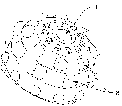
[0029] The difference from the PDC cone embodiment 1 is that the PDC composite sheet 8 adopts flat teeth, and the value range of the cutting layer chamfer R is 0.8~3.

Embodiment 3

[0031] The difference from PDC cone embodiment 1 lies in the number of auxiliary cones, which can be 0, 1, 2, or 3.

[0032] PDC cone embodiment 4

[0033] The difference from the embodiment of the PDC cone lies in the diameter of the PDC composite sheet 8, which ranges from 8 mm to 26 mm.

Embodiment 1

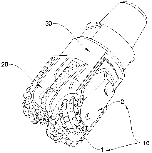
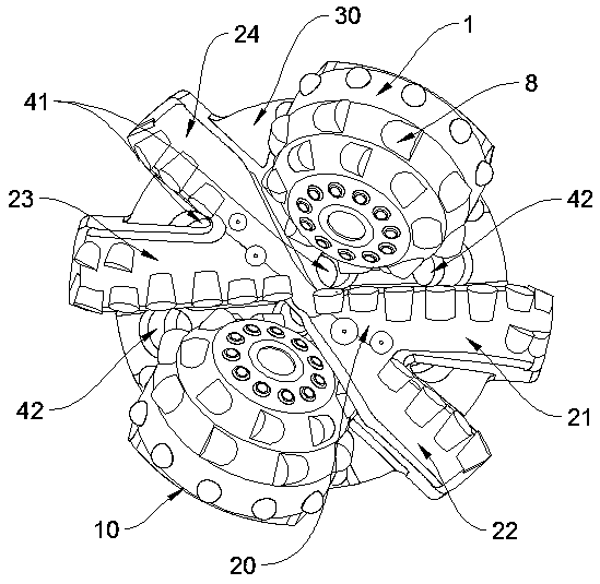
[0035] Such as figure 2 and image 3As shown, a compound drill bit is provided with a PDC cutter set 20 on the drill bit body 30, including four PDC cutting wings, which are the first main cutter wing 21, the first auxiliary cutter wing 22, the second main cutter wing 23 and the second auxiliary cutter wing. Blade 24. The bit body 30 between the first main blade 21 and the second auxiliary blade 24 and between the first auxiliary blade 22 and the second main blade 23 passes through the tooth palm 2 respectively. Two groups of above-mentioned PDC cones 10 are fixedly installed.

[0036] The PDC cutter set 20 is X-shaped, and the drill bit body 30 is provided with a type of water hole 41 near the intersection point of X for cleaning and cooling the PDC cutting wings.

[0037] The bit body 30 is provided with a second type of water hole 42 at the area between the first main blade 21 and the PDC cone 10, and at the area between the second main blade 23 and the PDC cone 10 , f...


PUM


Abstract

The invention provides a PDC tooth wheel. The conical face of the tooth wheel is regularly provided with a plurality of transversely-embedded PDC composite pieces in a staggered mode. The PDC tooth wheels are regularly fixed between cutting wings of a PDC drill bit to constitute a PDC tooth wheel composite drill bit. The transversely-embedded PDC composite pieces are adopted instead of an existingtooth wheel sharp tooth structure, so that on the one hand, the exposed height of cutting teeth is effectively decreased, diversified modes such as shearing, cutting and impacting are adopted insteadof an original single impacting rock breaking mode, the amplitude of longitudinal vibration of a tooth wheel drill bit is effectively decreased, the work mode of the tooth wheel drill bit in the composite drill bit is made to be matched with the PDC drill bit, and thus the attachment degree of the drill bit and the well bottom is increased, so that the drilling efficiency of the PDC drill bit isensured, and the mechanical drilling speed of the composite drill bit is advantageously increased; and on the other hand, by increasing the cutting chamfers of the PDC composite pieces, the work pressure of the PDC composite pieces is remarkably reduced, the invalid condition of the cutting teeth is advantageously relieved, and thus the service life of the drill bit is prolonged.

Description

technical field [0001] The invention relates to the technical field of oil drilling, in particular to a PDC cone and a composite drill bit containing the PDC cone. Background technique [0002] In routine operations, the service life of the drill bit and the ROP are two important indicators used to evaluate the cost performance of the drill bit. The service life of the drill bit determines the number of trips to replace the drill bit, and the ROP determines the operation time, so the above two parameters directly affect the drilling cost. Drill bit manufacturers continue to improve drill bit structure, cutter structure and other measures in order to meet the requirements of reducing the total cost of drilling. Among them, the Kymera composite drill bit technology launched by Baker Hughes is more representative - combining the roller cone bit and the PDC bit on the same bit body, so as to have the superior cutting ability and durable working performance of the PDC bit at the...

Claims


Application Information

Patent Timeline
Patent Type & Authority Applications(China)
IPC IPC(8): E21B10/52
Inventor 彭金龙匡晓勇曾凡杰
Owner 四川奥格特金刚石钻头有限公司
Why Eureka
Try Eureka