Heat pipe and heat-radiating device using same

A heat pipe and pipe body technology, applied in the field of heat pipes and heat dissipation devices using the heat pipe, can solve the problems of affecting the heat conduction performance of the heat pipe, breaking the capillary structure of the heat pipe, and insufficient strength of the heat pipe, so as to improve the heat conduction performance, increase the strength, and enhance the return flow speed effect

Active Publication Date: 2011-04-06
SHANGHAI MUNICIPAL ELECTRIC POWER CO +1
View PDF5 Cites 9 Cited by
  • Summary
  • Abstract
  • Description
  • Claims
  • Application Information

AI Technical Summary

Problems solved by technology

However, due to the insufficient strength of the existing heat pipe, it is easy to deform when it is tightly matched with the radiator, which will break the capillary structure in the heat pipe and affect the thermal conductivity of the heat pipe.

Method used


Image

  • Heat pipe and heat-radiating device using same
  • Heat pipe and heat-radiating device using same
  • Heat pipe and heat-radiating device using same

Examples


Embodiment Construction

[0015] The heat pipe of the present invention and the heat dissipation device using the heat pipe will be further described below with reference to the accompanying drawings.

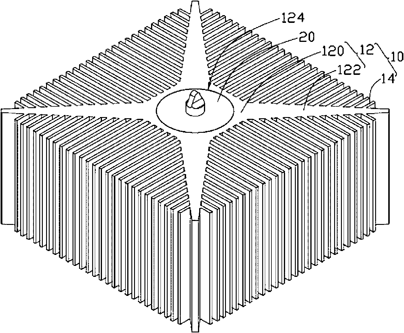
[0016] like figure 1 As shown, the heat dissipation device includes a heat sink 10 and a heat pipe 20 passing through the heat sink 10 .

[0017] The overall shape of the heat sink 10 is generally rectangular, and includes a central portion 12 and a plurality of cooling fins 14 radially extending from the periphery of the central portion 12 . The central portion 12 includes a cylinder 120 and four heat-conducting branch portions 122 extending from the periphery of the cylinder 120 . The cylinder 120 is a quadrangular prism, and a circular perforation 124 is formed at the center of the cylinder 120 through which the heat supply pipe 20 penetrates. The perforation 124 penetrates from the top surface of the cylinder 120 to the bottom surface thereof. The heat-conducting branch portions 122 radiate outwar...


PUM


Abstract

The invention relates to a heat pipe and a heat-radiating device using the same. The heat-radiating device comprises a heat radiator, wherein the heat pipe is combined with a punch hole on the heat radiator by interference fit, the heat pipe comprises a pipe body and a capillary structure arranged on the internal surface of the pipe body, a bracket is arranged in the axial direction in the pipe body, the bracket is butted against the capillary structure in the pipe body and is erected in the pipe body to divide the internal space of the pipe body into multiple parts, and the external surface of the bracket is provided with a capillary structure. By using the bracket, the strength of the heat pipe is improved and the deformation produced in the combining process of the heat pipe and the heat radiator by interference fit is prevented.

Description

technical field [0001] The invention relates to a heat pipe and a heat dissipation device using the heat pipe, in particular to a heat pipe with relatively high strength and a heat dissipation device using the heat pipe. Background technique [0002] At present, heat pipes are widely used in heat dissipation of electronic components with large heat generation due to their fast heat transfer speed. The existing heat pipe usually includes a hollow shell, a capillary structure arranged on the inner surface of the shell, and an appropriate amount of working fluid filled in the shell. One end of the heat pipe is the evaporating end, and the other end is the condensing end. In specific applications, the evaporating end of the heat pipe is in contact with a heating electronic component to absorb the heat generated by the heating electronic component and conduct it to its condensing end. The condensing end is connected with a radiator to further dissipate heat to the outside. [0...

Claims


Application Information

Patent Timeline
Patent Type & Authority Applications(China)
IPC IPC(8): F28D15/04F28F9/013H05K7/20
CPCF28D15/046F28F1/14F28D15/0283G06F1/20H01L23/427H01L2924/0002H01L2924/00
Inventor 余方祥郭哲豪
Owner SHANGHAI MUNICIPAL ELECTRIC POWER CO
Why Eureka
Try Eureka