Mirror device and optical apparatus

Active Publication Date: 2010-04-27
FUJITSU LTD
View PDF4 Cites 0 Cited by
  • Summary
  • Abstract
  • Description
  • Claims
  • Application Information

AI Technical Summary

Benefits of technology

[0055]In this manner, according to the present invention, it is possible to minimize PDL by means of setting the crystal axis direction of a crystal member itself with respect to the angle of input / output light, in accordance with the tilt angle setting to input / output light.

Problems solved by technology

However, the above patent documents 1 through 3 propose effects of birefringence onto only a single beam, and they do not propose a construction for suppressing PDL on the assumption of multiple modes of angles with respect to the crystal axis of the sapphire glass at the time input light and output light to movable mirrors pass through the sapphire glass which forms a permeable window.

Method used


Image

  • Mirror device and optical apparatus
  • Mirror device and optical apparatus
  • Mirror device and optical apparatus

Examples


Embodiment Construction

)

[0072]Hereinafter, one preferred embodiment of the present invention will be described with reference to the relevant accompanying drawings.

[0073]In this instance, the present invention should by no means be limited to the following embodiment. Further, the following disclosure of the present embodiment also clarifies not only the above described objects of the present invention but also other technological issues, means for resolving the issues, and effects and benefits of the present invention.

[0074][A] Construction of Mirror Device 10 according to the Present Embodiment:

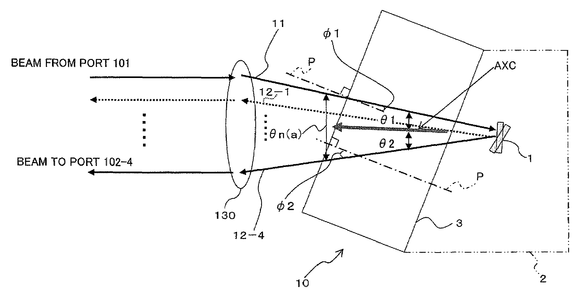
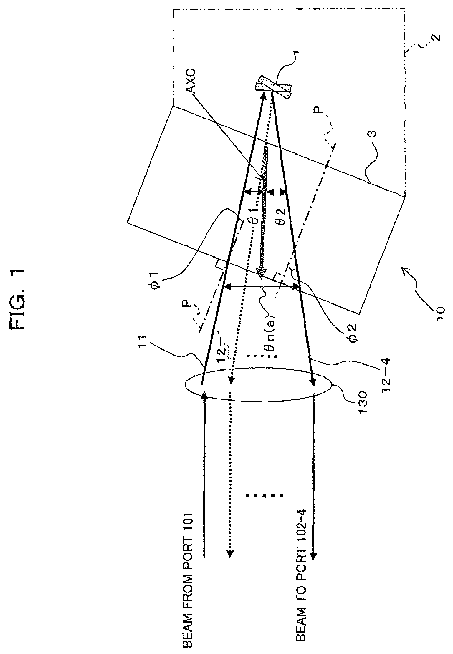
[0075]FIG. 1 is a diagram illustrating a mirror device according to the present embodiment. The mirror device 10 can be applied instead of the mirror device 140 of the optical apparatus 100 which is the wavelength selective switch illustrated in FIG. 15(a) and FIG. 15(b) whose description was already made. In this instance, FIG. 1 omits illustration of an input / output optical system 110, a spectral element 120, a...


PUM


Abstract

The present mirror device for suppressing PDL on the assumption of multiple modes of angles of input light and output light to movable mirrors with respect to the crystal axis of a crystal member at the time light passes through the crystal member. The mirror device includes a mirror system 2 and a flat-shaped crystal member 3 which is arranged in such a manner that a first angle is not larger than a second angle. The crystal member is constructed in such a manner that a third angle is substantially equal to a half of a fourth angle.

Description

BACKGROUND OF THE INVENTION[0001]1) Field of the Invention[0002]The present invention relates to a mirror device and an optical apparatus suitable for use in an optical communications system.[0003]2) Description of the Related Art[0004]As is widely well known in these days, to convert networks with Wavelength Division Multiplexing (WDM) as the core thereof into optical networks, has been progressed in high speed, in order to accommodate outstandingly increasing internet traffic. Although WDM of these days mainly has a point-to-point network form, it is expected that it will advance to ring-shaped networks and mesh-formed networks in the near future.[0005]To support this, each of the nodes forming a network will be capable of performing processing such as add / drop of an arbitrary wavelength, thereby making it possible to perform processing of whole Optical Cross Connect (OXC) without electric conversion so that dynamic setting / releasing of paths will be performed on the basis of wave...

Claims


Application Information

Patent Timeline
Patent Type & Authority Patents(United States)
IPC IPC(8): G02B26/00
CPCG02B6/29311G02B6/3512G02B6/356G02B6/29313G02B1/02G02B26/0833
Inventor AOTA, HIROFUMISHIBATA, KOHEIAKASHI, TAMOTSUYAMAMOTO, TSUYOSHI
Owner FUJITSU LTD
Why Eureka
Try Eureka