High dispersion diffraction grating including multiple holographic optical elements

a holographic optical element and high dispersion technology, applied in the field of diffraction gratings, can solve the problems of complex overall system, difficult arrays, practical upper limit of arrayed waveguides, etc., and achieve the effects of reducing pdl, reducing complexity, and reducing complexity

Active Publication Date: 2006-08-17
WASATCH PHOTONICS
View PDF11 Cites 5 Cited by
  • Summary
  • Abstract
  • Description
  • Claims
  • Application Information

AI Technical Summary

Benefits of technology

[0016] In a class of embodiments, the invention is a diffraction grating having at least two holographic optical elements (HOEs), including a Dickson grating and at least one other volume phase grating (VPG). The refractive index modulations of the Dickson grating's volume phase medium should have significantly greater spatial frequency than do those of each other VPG of the inventive grating, to ensure that the inventive grating has high dispersion for both S-polarized and P-polarized components of incident radiation (e.g., incident radiation having a range of wavelengths), minimized PDL, and preferably also, uniformly (or substantially uniformly) high diffraction efficiency across a broad wavelength range of incident radiation for both S-polarized and P-polarized components of the incident radiation. In a class of preferred embodiments, the refractive index modulations of the Dickson grating's volume phase medium have spatial frequency greater by at least a factor of two than do those of each other VPG of the inventive grating. In typical embodiments, the inventive grating not only has key desirable characteristics of a Dickson grating (minimized PDL, high S-polarization diffraction efficiency, and high P-polarization diffraction efficiency) but also provides higher dispersion (for both S-polarized and P-polarized components of incident radiation) than can be achieved by a Dickson grating or an optical device including a single diffraction grating (e.g., a Dickson grating) and one or more non-grating elements. Typically, the elements of the inventive grating are coupled to each other by suitable transparent adhesive. Typical embodiments of the inventive grating can be manufactured at an acceptably low cost, with a sufficiently small size, and with sufficiently high dispersion (for both S-polarized and P-polarized components) to be useful in many WDM (and other) applications requiring high dispersion.

Problems solved by technology

For systems with large numbers of channels (e.g., 16 or more) thin film filters are not suitable because the insertion loss is excessive and the overall system becomes too complex.
Arrayed waveguides are very complex so that large arrays are difficult to make and some means of temperature control is generally required.
This complexity places a practical upper limit on the number of channels that can be delivered with arrayed waveguides.
Typically, arrayed waveguides also have high insertion loss.
Fiber Bragg gratings have the same insertion loss problem as thin film filters—the insertion loss becomes excessive for large numbers of channels and, as with thin film filters, the overall system becomes unacceptably complex for a large number of channels.
All three of the above technologies have a relatively high cost per channel as the number of channels increases.
This creates a problem known as Polarization Dependent Loss (“PDL”) in WDM where components of radiation incident on a diffraction grating have different polarizations, since these components will be diffracted by the grating with different diffraction efficiencies.
This low grating frequency reduces the dispersion of the grating, making it more difficult to insert more channels and get good channel separation.
While PDL can be minimized in a conventional VPG, doing so either causes the overall diffraction efficiency to be low or the dispersion to be low, resulting in either unacceptably high insertion loss or relatively fewer available channels.
However, U.S. Pat. No. 6,750,995 does not teach how to implement a Dickson grating with sufficiently high dispersion (and sufficiently small size and low manufacturing cost) for some applications.
However, U.S. Pat. No. 5,602,657 does not disclose how to implement a diffraction grating having high dispersion for both S-polarized and P-polarized components of incident radiation (e.g., incident radiation having a range of wavelengths), minimized PDL, and at least substantially uniformly high diffraction efficiency across a broad wavelength range of incident radiation for both S-polarized and P-polarized components of the incident radiation.

Method used


Image

  • High dispersion diffraction grating including multiple holographic optical elements
  • High dispersion diffraction grating including multiple holographic optical elements
  • High dispersion diffraction grating including multiple holographic optical elements

Examples


Embodiment Construction

[0043] The term “transparent” is used herein with reference to an optical element (or component thereof) to denote transmissive to electromagnetic radiation that the optical element is designed to transmit and / or reflect.

[0044] The expression “high dispersion” is used herein with reference to the inventive multi-HOE grating (e.g., to indicate that an embodiment of the inventive grating is configured to diffract incident radiation with “high dispersion”) to denote that the inventive grating diffracts incident radiation with greater dispersion than its constituent Dickson grating (or one of its constituent Dickson gratings) would diffract the same radiation.

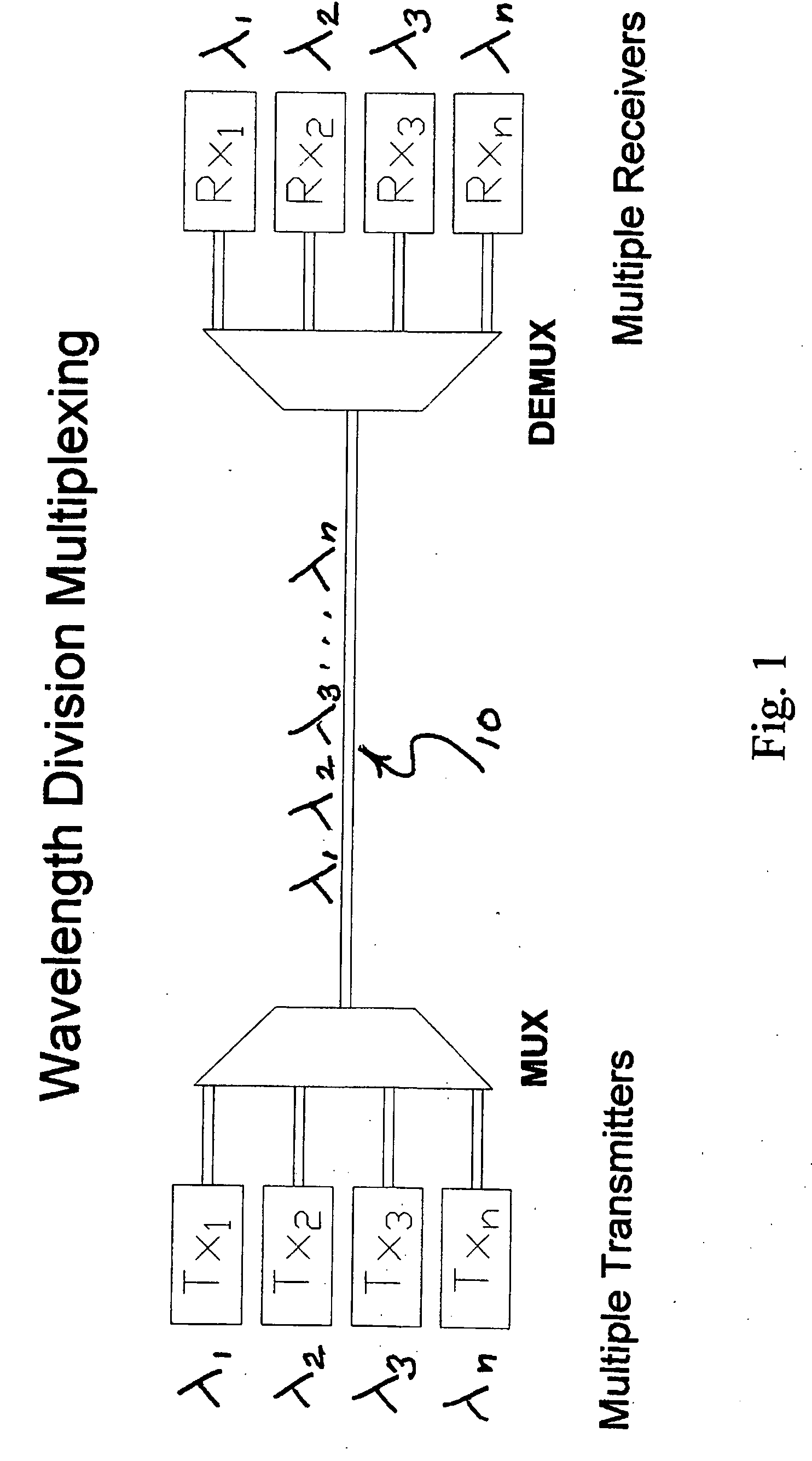
[0045]FIG. 1 is a block diagram of the Wavelength Division Multiplexing portion of a telecommunications system. The incoming beams from multiple sources (Tx1, Tx2, Tx3, Txn) with corresponding multiple carrier wavelengths (λ1, λ2, λ3, λn) are combined into a single beam in a multiplexer (MUX) and transmitted along a single optica...


PUM


Abstract

A diffraction grating having multiple holographic optical elements (HOEs), including a Dickson grating and at least one other volume phase grating (VPG). In typical embodiments, the multi-HOE grating is implemented to provide high dispersion, at least substantially uniform diffraction efficiency and at least substantially equal diffraction efficiencies for all polarizations across a wide range of wavelengths. The refractive index modulations of the Dickson grating's volume phase medium preferably have significantly greater spatial frequency than those of each other VPG of the multi-HOE grating. Typical embodiments of the multi-HOE grating can be manufactured at low cost with sufficiently small size and high dispersion (for both S-polarized and P-polarized radiation) to be useful in Dense Wavelength Division Multiplexing (DWDM) applications and other applications requiring high dispersion. The multi-HOE grating can be implemented as a transmissive or reflective grating.

Description

FIELD OF THE INVENTION [0001] The invention pertains to diffraction gratings (e.g., volume phase gratings implemented as holograms) and holographic optical elements (“HOEs”). In preferred embodiments, the invention is a diffraction grating that has high dispersion and includes multiple HOEs. BACKGROUND OF THE INVENTION [0002] The telecommunications industry is growing rapidly as a result of the expanding need for the transmitting and receiving of greater amounts of information. The industry, in order to meet the needs of the market, has developed a number of technologies that make use of the inherent broadband capabilities of fiber optics. One of these technologies is Wavelength Division Multiplexing, or WDM. [0003] WDM allows many signals to be transmitted simultaneously along a single optical fiber by sending each signal on a different carrier. Each carrier is a light beam of a slightly different wavelength than that of all of the other carriers. In order to combine these individu...

Claims


Application Information

Patent Timeline
Patent Type & Authority Applications(United States)
IPC IPC(8): G02B6/34
CPCG02B5/32G02B6/29311G02B6/2938
Inventor CIFELLI, DANDICKSON, LEROY DAVIDRALLISON, RICHARDPEARSON, ELROY
Owner WASATCH PHOTONICS
Why Eureka
Try Eureka