
Seal assembly for hub flange and slinger

a hub flange and slinger technology, applied in mechanical devices, braking systems, transportation and packaging, etc., can solve the problem of muddy water entering the bearing portion, and achieve the effect of positively preventing muddy water

Inactive Publication Date: 2010-05-04
JTEKT CORP
View PDF9 Cites 7 Cited by
  • Summary
  • Abstract
  • Description
  • Claims
  • Application Information

AI Technical Summary

Benefits of technology

[0005]This invention has been made in order to solve the above problem, and an object of the invention is to provide an axle bearing apparatus in which muddy water is positively prevented from intruding into a bearing portion from an outer periphery, bolt holes, etc., of the flange through a clearance between the flange and a slinger.
[0010]In the present invention, the O-ring or the seal member is interposed between the flange of the hub shaft and the slinger between which muddy water is liable to intrude, and as another alternative, the flange and the slinger are adhesively bonded together by the adhesive. Therefore, muddy water is positively prevented from intruding into the bearing portion through a clearance between the flange and the slinger.

Problems solved by technology

Therefore, there has been a fear that muddy water might intrude into the bearing portion from the outside of the rotary flange and the bolt holes through a clearance between the rotary flange and the annular portion of the slinger.

Method used


Image

  • Seal assembly for hub flange and slinger
  • Seal assembly for hub flange and slinger
  • Seal assembly for hub flange and slinger

Examples


first embodiment

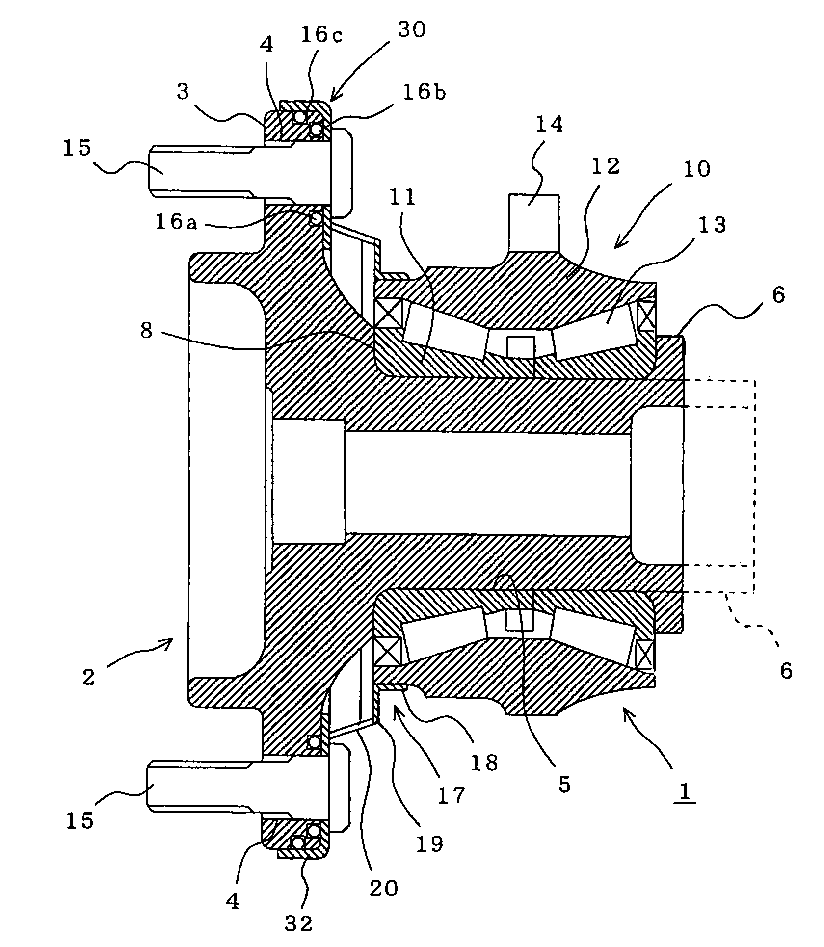
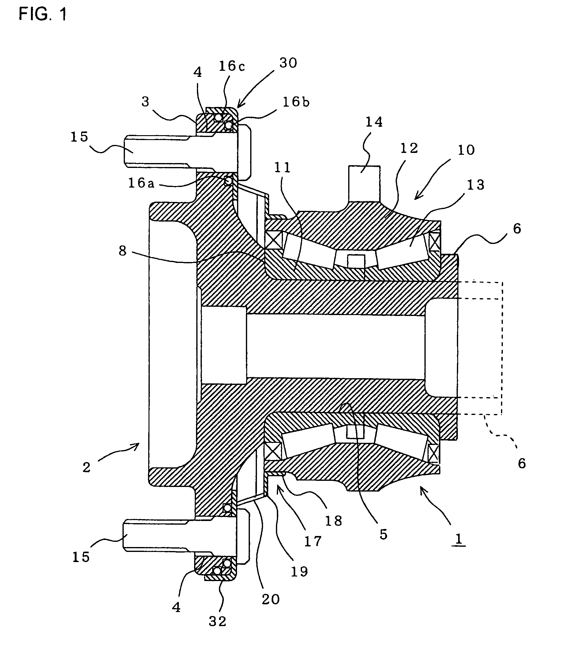
[0020]FIG. 1 is a vertical cross-sectional view of an axle bearing apparatus according to a first embodiment of the present invention. In the following description, the right side in the drawings will be referred to as “inner side”, while the left side will be referred to as “outer side”.

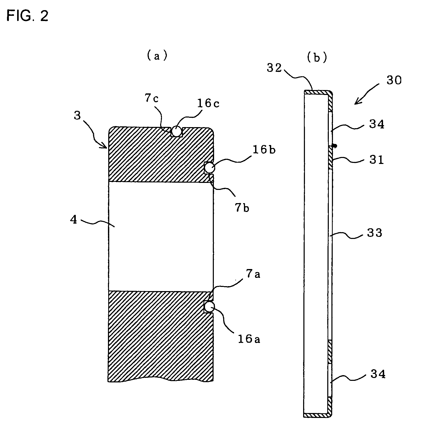
[0021]In the drawings, reference numeral 1 denotes the axle bearing apparatus of the invention, and a flange 3 is formed on an outer periphery of a hub shaft 2 (made of a steel material) at an outer end portion thereof, and a plurality of bolt holes 4 are formed through this flange 3. Bolts 5 are passed respectively through these bolt holes 4 so as to mount a wheel (not shown) on the flange 3. A cylindrical portion 5 for the mounting of a bearing portion 10 (described later) thereon is formed on a central portion of the inner side of the flange 3, and projects therefrom in an axial direction. A cylindrical caulking portion 6 (indicated in broken lines) for fixing the bearing portion 10 is formed in ...

second embodiment

[0034]FIG. 4 is a cross-sectional view of a half portion of an axle bearing apparatus according to a second embodiment of the invention on one side of a centerline (longitudinal axis) thereof. Those portions identical to those of the first embodiment will be designated by identical reference numerals, respectively, and explanation thereof will be omitted.

[0035]In this embodiment, a slinger 30 is composed solely of a body portion 31, and therefore does not have the rib 32 as described above for the first embodiment. Furthermore, the O-rings 16a to 16c as described above for the first embodiment are not interposed between a flange 3 of a hub shaft 2 and the slinger 30 (Therefore, the grooves 7a to 7c are not formed in the flange 3), and the slinger 30 is adhesively bonded to an inner side surface of the flange 3 by an adhesive 36. In this embodiment, the rib 32 may be formed at the outer periphery of the body portion 31 as in the first embodiment.

[0036]In this embodiment, also, simila...

third embodiment

[0037]FIG. 5 is a cross-sectional view of a half portion of an axle bearing apparatus according to a third embodiment of the invention on one side of a centerline (longitudinal axis) thereof. Those portions identical to those of the second embodiment will be designated by identical reference numerals, respectively, and explanation thereof will be omitted.

[0038]In this embodiment, a seal member 37 made of an elastic material such as rubber is interposed between a slinger 30 (which has the same structure as that of the slinger 30 of the second embodiment) and an inner side surface of a flange 3 of a hub shaft 2. The seal member 37 may be provided over an entire area of contact between the slinger 30 and the flange 3, or may be provided only at an area disposed radially inwardly of a circle of bolt holes 4 or only at areas disposed respectively around the bolt holes 4.

[0039]In this embodiment, also, similar advantageous effects to those of the first embodiment can be obtained.


PUM


Abstract

An axle bearing apparatus includes a hub shaft including a wheel-mounting flange formed at its outer end portion, and a cylindrical portion formed on an inner side surface of the flange, a bearing portion press-fitted on the cylindrical portion of the hub shaft and including an inner ring, an outer ring and rolling elements disposed between the inner and outer rings, and a slinger having a through hole formed through its central portion. The through hole is fitted on the cylindrical portion such that an outer diameter of the slinger is generally equal to an outer diameter of the flange, and the slinger is press-clamped to the inner side surface of the flange by bolts press-fitted respectively in a plurality of bolt holes formed in the flange. O-rings are interposed between the flange and the slinger.

Description

BACKGROUND OF THE INVENTION[0001]This invention relates to an axle bearing apparatus, and more particularly to an axle bearing apparatus having muddy water intrusion prevention means for preventing muddy water from intruding into a bearing portion.[0002]Recently, unit-type axle bearing apparatuses have increasingly been used even in a pickup truck, etc., and therefore these bearing apparatuses are required to have a higher muddy water-proof ability.[0003]There is known an axle bearing apparatus having such a muddy water-proof ability, in which a seal ring comprising a metal core and a seal member is fixed to an outer end portion of an outer ring of a bearing portion, and a slinger is fixed to an axial inner side surface of a rotary flange, and is held in sliding contact with the seal ring, thereby closing an opening of the bearing portion (see, for example, JP-A-2005-233287).[0004]In the axle bearing apparatus of JP-A-2005-233287, an annular portion of the slinger is not disposed in...

Claims


Application Information

Patent Timeline
Patent Type & Authority Patents(United States)
IPC IPC(8): B60B35/18
CPCB60B27/00F16C33/805F16C19/386F16C2326/02
Inventor INOUE, SHIGERUMUROTANI, CHIKAYOSHIFURUSAWA, SHIGEAKIHARADA, TAKUMIKOMA, YUTAKA
Owner JTEKT CORP
Learn More