
Camera-ready copy sheet for lithograpic printing plate

a technology of lithographic printing plate and copy sheet, which is applied in the direction of printing press, mounting board, printing, etc., can solve the problems of low dimensional stability, reducing the position accuracy, and the softness of the base tending to reduce the accuracy of positions

Inactive Publication Date: 2002-06-18
FUJIFILM HLDG CORP
View PDF12 Cites 0 Cited by
  • Summary
  • Abstract
  • Description
  • Claims
  • Application Information

AI Technical Summary

Benefits of technology

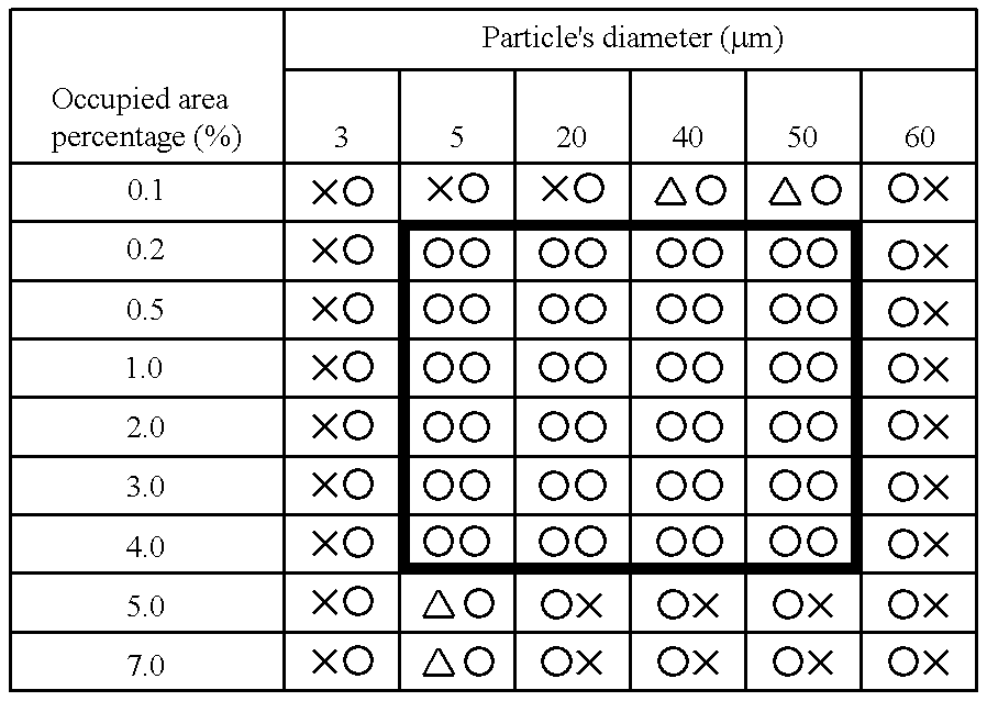
The present inventors conducted intensive studies in order to attain the stated object of the invention. As a result, it was found that by using a camera-ready copy sheet having asperities of a predetermined shape on the front side that are urged against the back side of a lithographic printing plate to depress it and in which the height of the projections in the asperities ranges from 5 .mu.m to 50 .mu.m and the sum per unit area of maximum cross-sectional areas of planes in said projections that are parallel to the surface of the sheet ranges from 0.2% to 4% of the unit area, the plate with which lithographic printing is being performed on a press can be positively prevented from being positionally offset on a plate cylinder primarily under the printing pressure. The present invention has been accomplished on the basis of this finding.
The fine particles to be used in forming asperities in the camera-ready copy sheet of the present invention are those having high hardness and ranging from 5 .mu.m to 50 .mu.m in diameter and examples include fine inorganic particles such as glass beads and the fine particles of comparatively hard polymers such as polystyrene. If the particles are coarsely distributed to occupy 0.2-4% of unit area, there is no need to use as large a number of fine particles as specified in Unexamined Japanese Patent Publication (kokai) No. 11-20130(1999), supra; instead, a comparatively small number of fine particles suffice to achieve positive prevention of positional offset of lithographic plates on the plate cylinder.

Problems solved by technology

Compared to lithographic plates using metallic bases, those using non-metallic bases have good handling properties but, on the other hand, they do not have high dimensional stability.
When lithographic presswork is performed with plates having a non-metallic base on at least the back side, the softness of the base tends to reduce the accuracy of the positions in which the plate is gripped on to the leading edge of the plate cylinder.
As a further problem, the friction with the cylinder during printing causes local distortion in the plate, eventually reducing the accuracy in position relative to the paper to be printed.
Under these circumstances, the use of lithographic plates having a n on-metallic base on at least the back side has been limited to the case of short-run work where no problem is caused even if printed pieces have low accuracy in register on the other hand, exquisite multi-color printing and long-run work on massive presses often fail to achieve the desired color register.
Of the two distinctive advantages of the CTP technology, the ease in registration for multi-color printing cannot be realized with lithographic plates based on non-metallic materials such as paper and plastics because they have the problems already described above.
Since the fine particulate matter of the type used in the patent is generally expensive, adhering and fixing it at high and uniform density inevitably increases the cost of the sheet.
In addition, the fine particles cannot be easily dispersed in liquid at high concentration and, what is more, agglomeration often occurs in the highly concentrated dispersion and the resulting coarse particles will deteriorate the quality of printed matter.

Method used


Image

  • Camera-ready copy sheet for lithograpic printing plate

Examples


example

The surface of a polyethylene terephthalate (PET) base 100 .mu.m thick was roller coated with a homogenized dispersion of the recipe indicated below. This gave samples of the copy sheet according to the embodiment under consideration which had high areas formed on the surface from glass beads. The glass beads (GB 731 of Toshiba Glass Co., Ltd.) were classified to a size range of 3-60 .mu.m with a powder centrifuge and mixed with a binder acrylic resin (40% in toluene) in controlled ratios to prepare samples having different occupied area percentages.

(Prescription)

The lithographic printing plate was prepared by a dedicated platemaker SPM 415 from super Master Plus of AGFA-Gevaert AG which was a silver diffusion type light-sensitive material using a PET base 100 .mu.m thick. The plate had a total thickness of 130 .mu.m. The lithographic printing plate may be replaced by a PS plate having an image-receiving layer on a non-metallic base or an electrophotographically made plate.

The copy ...


PUM


Abstract

The present invention provides for a camera-ready copy sheet to be inserted between a plate cylinder and a lithographic printing plate at least the back side of which is made of a non-metallic material. The copy sheet has asperities of a predetermined shape on the front side that are urged against the back side of the lithographic printing plate to depress it. The height of the projections in the asperities ranges from 5 mum to 50 mum. The sum per unit area of maximum cross-sectional areas of planes in the projections that are parallel to the surface of the sheet ranges from 0.2% to 4% of the unit area.

Description

1. Field of the InventionThe present invention relates to camera-ready copy sheet for use with lithographic printing plates to ensure that they will not be positionally offset on plate cylinders in a press.2. Description of the Related ArtTo perform printing with lithographic presses, a lithographic plate is wrapped around a plate cylinder and fixed mechanically.Conventionally, the base of lithographic printing plates is made of either metals or non-metals such as plastics and paper. Compared to lithographic plates using metallic bases, those using non-metallic bases have good handling properties but, on the other hand, they do not have high dimensional stability.When lithographic presswork is performed with plates having a non-metallic base on at least the back side, the softness of the base tends to reduce the accuracy of the positions in which the plate is gripped on to the leading edge of the plate cylinder. If this phenomenon occurs, the accuracy of the plate in the vertical po...

Claims


Application Information

Patent Timeline
Patent Type & Authority Patents(United States)
IPC IPC(8): B41N6/00B41F27/00B41F27/14B41M1/06B41M1/00B41M9/00B41M9/02B41F27/08
CPCB41F27/14B41N6/00B41M9/02B41M1/06
Inventor NAKAYAMA, TAKAOKASAI, SEISHIOHISHI, HIROYUKI
Owner FUJIFILM HLDG CORP
Learn More