Drying device and ink-jet printing device equipped with the same

a technology of inkjet printing and drying device, which is applied in printing presses, other printing apparatus, printing, etc., can solve problems such as image quality degradation, and achieve the effects of sufficient evaporation energy, sufficient drying time relative to the printed object to be transported, and efficient drying

Active Publication Date: 2020-09-01
MIYAKOSHI PRINTING MACHINERY
View PDF8 Cites 0 Cited by
  • Summary
  • Abstract
  • Description
  • Claims
  • Application Information

AI Technical Summary

Benefits of technology

[0024]In the drying device of the present invention, since the first heating roller part and the second heating roller part are installed, the drying time relative to the printed object to be transported can be made sufficiently longer.
[0025]Moreover, by heating the two sides of the printed object by using the first heating roller part and the first heating part as well as the second heating roller part and the second heating part, the printed object can be efficiently dried.
[0026]At this time, in the drying device of the present invention, since the setting temperature of the second heating roller part is higher than the setting temperature of the first heating roller part, the wet printed object is sufficiently heated by the first heating roller part and the first heating part whose setting temperatures are comparatively low, and to the aqueous solvent, a sufficient evaporation energy can be applied by the second heating roller part and the second heating part whose setting temperatures are comparatively high. Additionally, by adding sufficient evaporation energy thereto, the aqueous solvent is evaporated to be removed from the printed object.
[0027]In this manner, in the drying device of the present invention, since the wet printed object immediately after the printing process can be heated step by step, the printed object can be positively dried, and it becomes possible to sufficiently suppress curling of the printed object itself or wrinkles and cockling from occurring in the printed object.
[0028]In this case, the setting temperature of the first heating roller part is desirably made the boiling point or less of the aqueous solvent contained in the ink. That is, in the first heating roller part, heating of the printed object is more preferentially carried out in comparison with the evaporation of the aqueous solvent. Thus, it becomes possible to positively prevent the temperature of the printed object from being abruptly raised.
[0029]In the drying device of the present invention, since the plural first hot air blowing devices are installed side by side along the circumferential direction of the first heating roller part as the first heating part, and since the plural second hot air blowing devices are installed side by side along the circumferential direction of the second heating roller part as the second heating part, the hot air can be blown to the printed object without irregularities. Thus, the printed object is suppressed from having partial differences in the drying speed and can be more uniformly dried.

Problems solved by technology

In the printed object immediately after the printing process from which the aqueous solvent needs to be removed as described above, when much time is required for removing the aqueous solvent, bleeding of ink onto the printing object due to insufficient drying of ink, flocculation of ink, mixed color with an ink having another color, retransferring to the printing object caused by an ink transferring process from a contact member to the printing surface and the like tend to occur, thereby causing a problem of degradation in image quality.

Method used


Image

  • Drying device and ink-jet printing device equipped with the same
  • Drying device and ink-jet printing device equipped with the same
  • Drying device and ink-jet printing device equipped with the same

Examples


Embodiment Construction

[0050]Referring to the Figures, the following description will discuss preferred embodiments of the present invention in detail. Additionally, in the drawings, the same components are indicated by the same reference numerals, and the overlapping descriptions will be omitted. Moreover, the positional relationship, such as upper, lower, left or right side, is based upon the positional relationship shown in the Figure, unless otherwise particularly specified. Furthermore, dimensional ratios of the Figures are not intended to be limited by the dimensional ratios shown in Figures.

[0051]First, an explanation will be given to a drying device in accordance with the present invention.

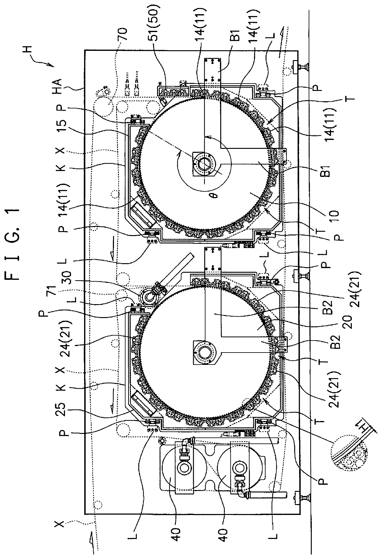
[0052]The drying device in accordance with the present invention is a device which dries a long-sized printed object corresponding to the printing object onto which an ink was applied by a printing part, while being transported.

[0053]The drying device may be used by being installed in a printing device, or may b...


PUM


Abstract

A drying device H is provided with: a first heating roller part 10 and a second heating roller part 20 that guide a printed object X and are capable of heating the printed object X; a first heating part 11 that is formed so as to be opposed to the outer circumferential surface of the first heating roller part 10 and a second heating part 21 that is formed so as to be opposed to the outer circumferential surface of the second heating roller part 20, wherein after the printed object X has been guided to the first heating roller part 10 on the upstream side, it is guided to the second heating roller part 20 on the downstream side, with the setting temperature of the second heating roller part 20 being made higher than the setting temperature of the first heating roller part 10, and an ink-jet printing device I equipped with such a heating device.

Description

TECHNICAL FIELD[0001]The present invention relates to a drying device and an ink-jet printing device equipped with the same, and more specifically, concerns a drying device for drying a printed object printed by a printing part and an ink-jet printing device equipped with the same.BACKGROUND ART[0002]A printing device for carrying out printing on a printing object, such as paper, film, cloth or the like, has been known.[0003]In general, such printing is carried out by applying an ink containing a coloring agent and an aqueous solvent onto a printing object so that a printed object is formed. For this reason, the printed object immediately after the printing process is in a wet state containing the aqueous solvent, and the corresponding aqueous solvent needs to be removed from the printed object.[0004]In the printed object immediately after the printing process from which the aqueous solvent needs to be removed as described above, when much time is required for removing the aqueous s...

Claims


Application Information

Patent Timeline
Patent Type & Authority Patents(United States)
IPC IPC(8): B41J11/00B41F23/04
CPCB41F23/042B41F23/0459B41J11/002B41J11/0015B41J11/0024B41J11/0022
Inventor IZAWA, HIDEOOOYAMA, KOUICHISATO, KAZUSHIGEKON, HIDETOSHI
Owner MIYAKOSHI PRINTING MACHINERY
Why Eureka
Try Eureka