Connector with terminal fittings press fit in a base wall of a connector housing

a technology of connecting rods and connector housings, applied in the direction of coupling device details, coupling device connections, securing/insulating coupling contact members, etc., can solve the problem of unfavorable shaking of the terminal fittings, and achieve the effect of preventing loose movement of the projecting portion

Active Publication Date: 2010-05-04
SUMITOMO WIRING SYST LTD
View PDF10 Cites 12 Cited by
  • Summary
  • Abstract
  • Description
  • Claims
  • Application Information

AI Technical Summary

Benefits of technology

[0007]The invention relates a connector with a housing with a base wall and through holes that penetrate the base wall in a thickness direction. Terminal fittings are insertable into the through holes. Each terminal fitting is long and narrow, and has at least one projection projecting out in a width direction. At least one press-in portion is located before the projection with respect to an inserting direction and is pressed into a space defined by the inner surface of the through hole. At least one inclination is formed on the inner surface of each through hole and is narrowed towards the front with respect to the inserting direction of the terminal fitting from one end surface of the base wall. The inclination is at a position corresponding to the projection for guiding the terminal fitting. At least one substantially straight portion is located before the inclination with respect to the inserting direction of the terminal fitting and extends in the inserting direction towards the other end surface of the base wall. The straight portion has at least one press-in area for the press-in portion. At least one restriction defines at least one step together with the substantially straight portion and extends from a taper end of the inclined portion to the step for tightly holding a front area of the projection with respect to the inserting direction while preventing loose movements of the projecting portion.
[0008]Front areas of the projections with respect to the inserting direction are held tightly by the restrictions of the through holes while having loose movements thereof prevented. Thus, the terminal fittings are positioned and aligned. Accordingly, the press-in portions do not require large press-in margins engageable with the press-in areas for alignment adjustment and inserting forces for the terminal fittings can be reduced.
[0010]The substantially straight portion of each through hole preferably includes at least one recess that does not contact a plate surface of the facing terminal fitting. Thus, the inserting force for the terminal fitting is reduced even further, and abrasion related damage on the plate surface of the terminal fitting is prevented.

Problems solved by technology

Thus, an external force is unlikely to shake the terminal fitting.

Method used


Image

  • Connector with terminal fittings press fit in a base wall of a connector housing
  • Connector with terminal fittings press fit in a base wall of a connector housing
  • Connector with terminal fittings press fit in a base wall of a connector housing

Examples


first embodiment

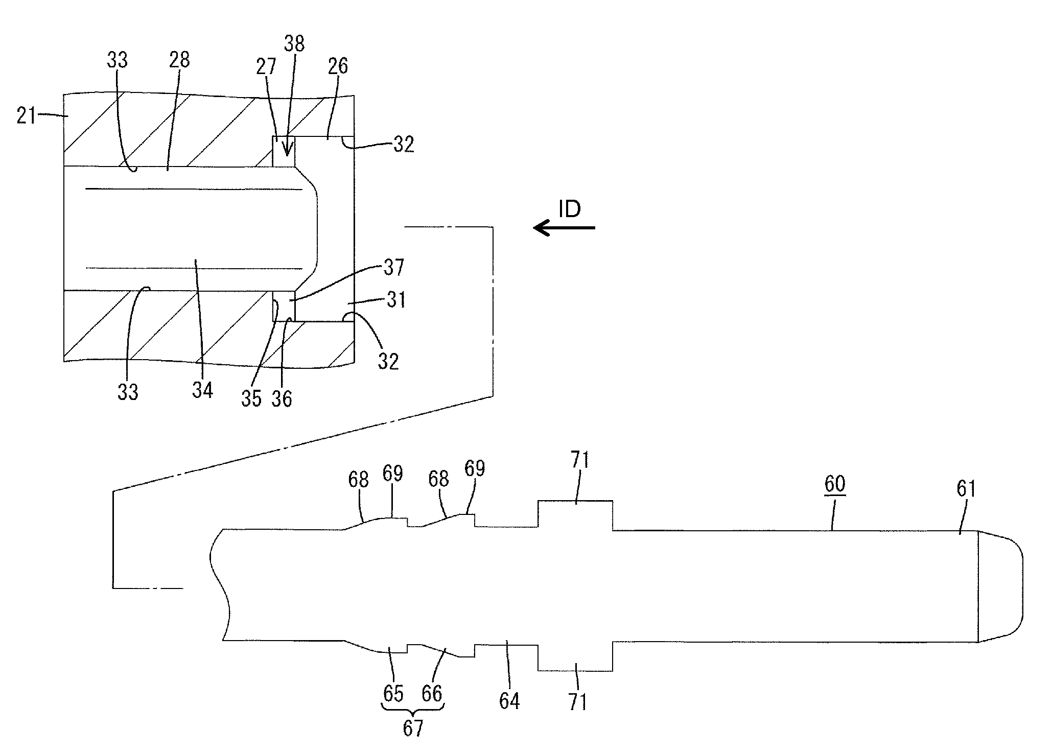
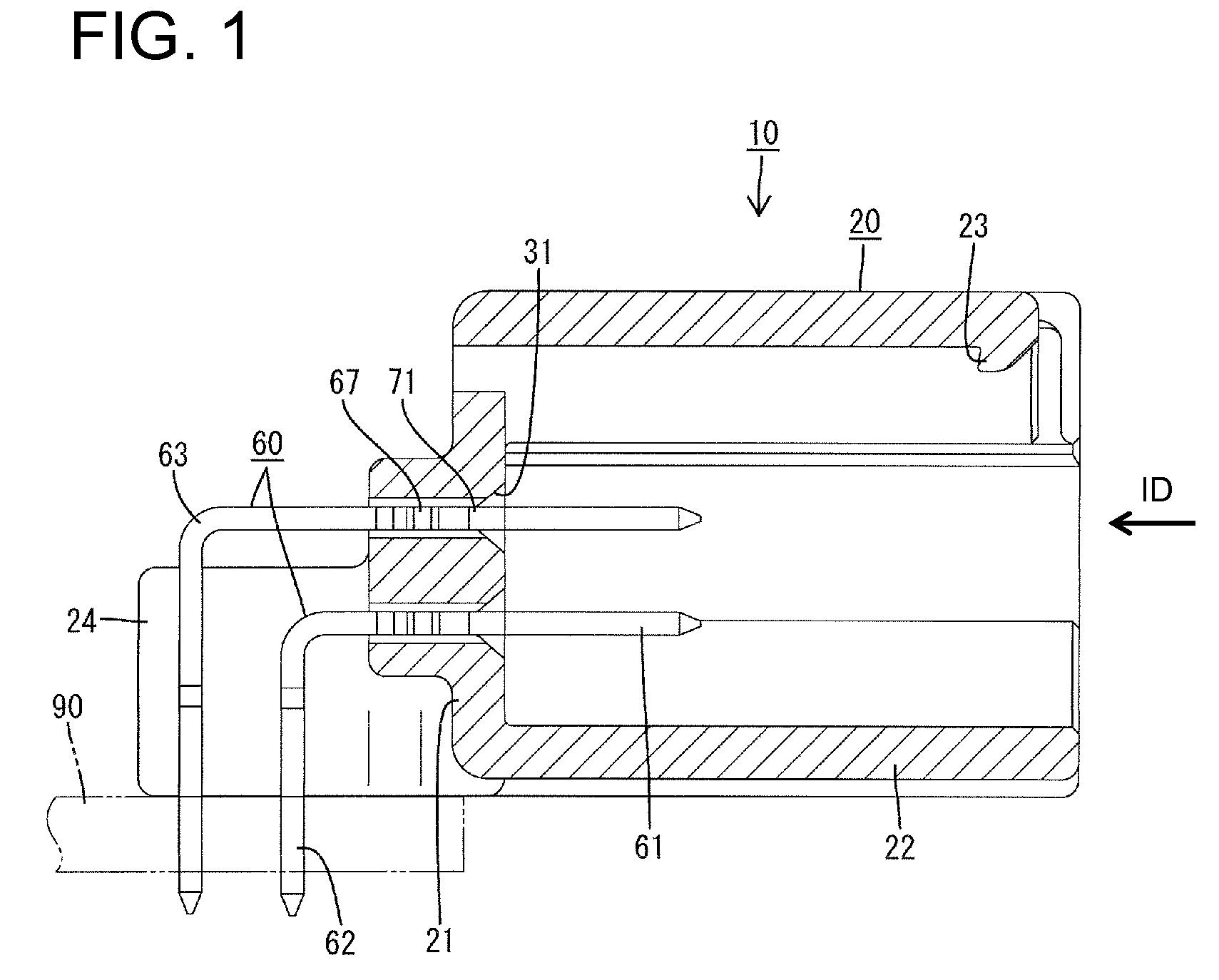
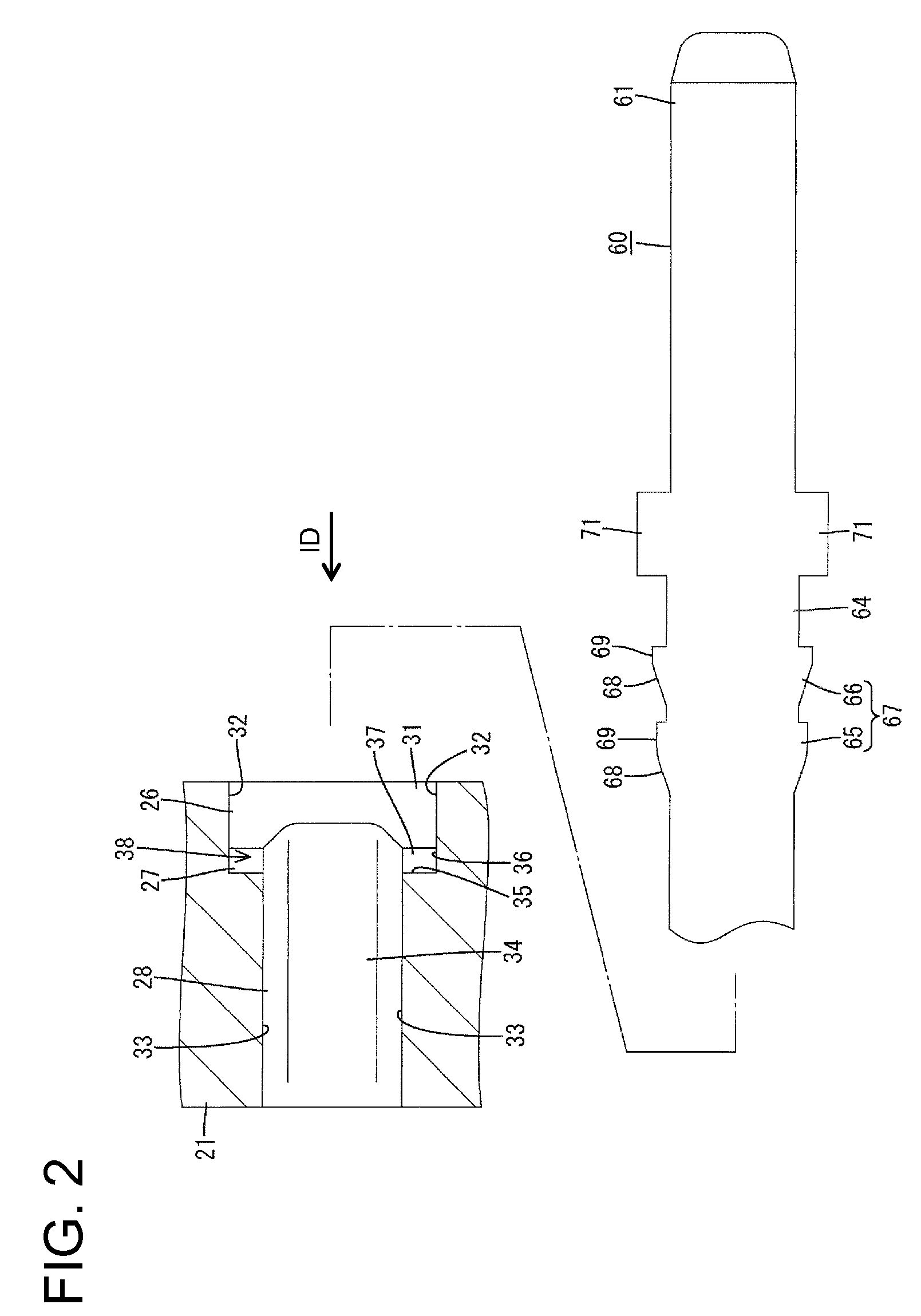
[0027]A connector according to the invention is described with reference to FIGS. 1 to 6. The connector has a housing 20 and terminal fittings 60, and is connectable with a mating connector (not shown) while being mounted on a circuit board 90. In the following description, and end that is to be connected with the mating connector is referred to as the front end.

[0028]Each terminal fitting 60 is formed unitarily by press-working an electrically conductive (preferably metal) plate and has a long, narrow, flat rectangular tab. As shown in FIG. 1, a terminal connecting portion 61 is defined at one end of the terminal fitting 60 and is configured to be connected with a mating terminal fitting. A board connecting portion 62 is formed at the opposite end of the terminal fitting 60 and is to be passed through a through hole of the circuit board 90. The leading ends of the terminal connecting portion 61 and the board connecting portion 62 are tapered for guiding purposes. This connector 10 ...

second embodiment

[0046] the widthwise intermediate part of the main portion 64 of the terminal fitting 60 does not contact the recessed surfaces 41 of the straight portion 28 during insertion of the terminal fitting 60 into the through hole 25. Thus, an inserting force for the terminal fitting 60 is low. In addition, after the insertion of the terminal fitting 60 into the through hole 25, the opposite widthwise sides of the main portion 64 of the terminal fitting 60 are adjacent to the flat surfaces 42 of the straight portion 28 and are sandwiched by the flat surfaces 42 of the straight portion 28. Thus, the terminal fitting 60 is prevented from shaking even upon the action of an external force.

[0047]The invention is not limited to the above described and illustrated embodiments. For example, the following embodiments are also embraced by the technical scope of the present invention as defined by the claims.

[0048]The front areas of the projections with respect to the inserting direction may be held ...


PUM


Abstract

A base wall (21) of a connector housing (20) is formed with through holes (25), into which terminal fittings (60) are insertable. The inner surface of each through hole (25) includes an inclined portion (26) narrowed toward the rear side from the front surface of the base wall (21) and arranged at a position corresponding to projections (71) for guiding the terminal fitting (60), a straight portion (28) located behind the inclined portion (26), extending in an inserting direction toward the rear surface of the base wall (21) and having a press-in area for press-in portions (67), and restricting portions (27) defining steps together with the straight portion (28), extending from a taper end of the inclined portion (26) to the steps (35) and tightly holding rear parts of the projections (71) while preventing loose movements.

Description

BACKGROUND OF THE INVENTION[0001]1. Field of the Invention[0002]The invention relates to a connector.[0003]2. Description of the Related Art[0004]Japanese Unexamined Patent Publication No. 2006-19228 relates to a circuit board connector with a housing. Through holes penetrate a base wall of the housing in a thickness direction and long narrow terminal fittings are inserted through the base wall. Each terminal fitting includes a press-in portion to be pressed into the through hole and a projection that projects out in width direction behind the press-in portion for limiting the penetration of the terminal fitting. Press-in areas are formed in middle parts of the through holes in forward and backward directions and receive the press-in portions of the terminal fittings. Recesses are formed in rear parts of the through holes. Front ends of the recesses and the rear ends of the press-in areas are connected via steps. Further, each recess has an inclined portion narrowed in an inserting ...

Claims


Application Information

Patent Timeline
Patent Type & Authority Patents(United States)
IPC IPC(8): H01R13/40
CPCH01R13/41H01R43/20H01R12/55
Inventor SHIBATA, TAKAHIROTANAKA, TSUTOMUMATSUSHITA, YASUO
Owner SUMITOMO WIRING SYST LTD
Why Eureka
Try Eureka