Airborne stabilized wind turbines system

a wind turbine and stabilizer technology, applied in the field of wind turbine systems, can solve the problems of limited land for building the towers to support such wind turbines, high construction cost, and intense vibration, and achieve the effect of angular stability

Inactive Publication Date: 2010-05-04
MELLER MOSHE
View PDF40 Cites 26 Cited by
  • Summary
  • Abstract
  • Description
  • Claims
  • Application Information

AI Technical Summary

Benefits of technology

[0009]It is an object of the present invention to provide the said system which will be angularly stable while being airborne.
[0025]In another version of the invention, the turbine section will include more than one wind turbine, these said turbines constructed in a way that when the wind is blowing through them they will rotate in opposite directions; therefore each one of the turbines will induce rotational torque on the system in opposite direction. These said opposite rotational torques will balance each other; but in order to avoid the rotating of the whole system the result of the torques acting on the system, must be zero, achieving zero torques result, requires a very accurate and complicated angular controller; this angular controller should continuously control the angle of attack of the wind turbines blades, the power that produced by the generators of the system and other things that can influence the magnitude of the torque that each turbine inducing on the system. The alternative to this complicated angular controller is system that utilizing the principle of the present invention in the same way that described above. The only different in this type of systems with more than one wind turbine, is that the required returning torque RT needs to balance only the differential unbalanced torque that has not been balanced by the opposite rotating turbines. And that can be achieved in low cost and in simple and reliable way, using the principle of the present invention.

Problems solved by technology

However, tall towers are expensive to build and once built, are subject to intense vibrations during operation.
Furthermore, land for building the towers to support such wind turbines is limited in view of numerous, known factors, including acquisition costs, environmental impact, zoning issues.
Although offshore winds, i.e., winds over bodies of water, are stronger than winds over land, the construction of support structures for wind turbines over a body of water is expensive, although there are significantly fewer limitations on the space for building support structures over such bodies of water.
The most notable limitation is that the construction of support structures for wind turbines is limited to certain depths of the bodies of water.
A drawback of this prior art system is that its power generation is very limited and it is not very efficient.
Among its drawbacks are that it is expensive to construct, includes complex mechanical parts and is not very practical.

Method used


Image

  • Airborne stabilized wind turbines system
  • Airborne stabilized wind turbines system
  • Airborne stabilized wind turbines system

Examples


Embodiment Construction

[0039]Referring to the accompanying drawings

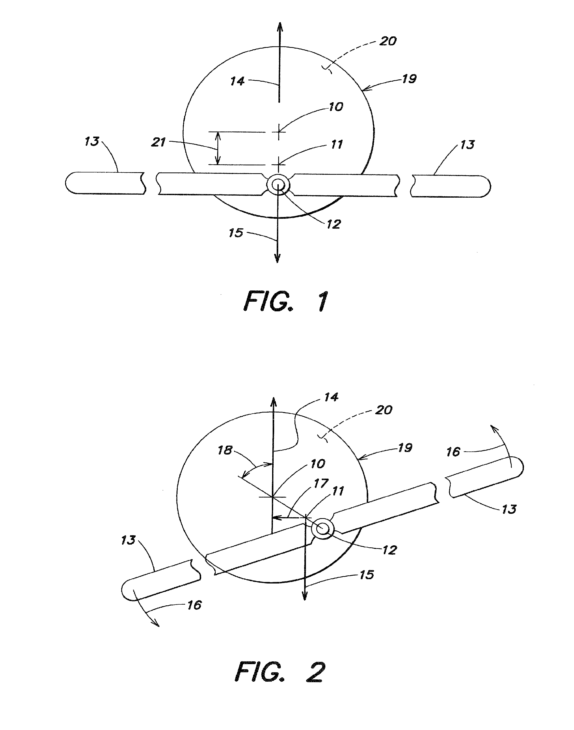
[0040]FIG. 1 and FIG. 2 are schematic drawings of the system of the present invention, many details are not showing in these drawings and will be showed and explained later, the purpose of these simple drawings is to explain the basic principals of the system of the present invention. 19 is sealed cylindrical body; 19 is filled with lighter than air gas 20, such as helium or hydrogen;

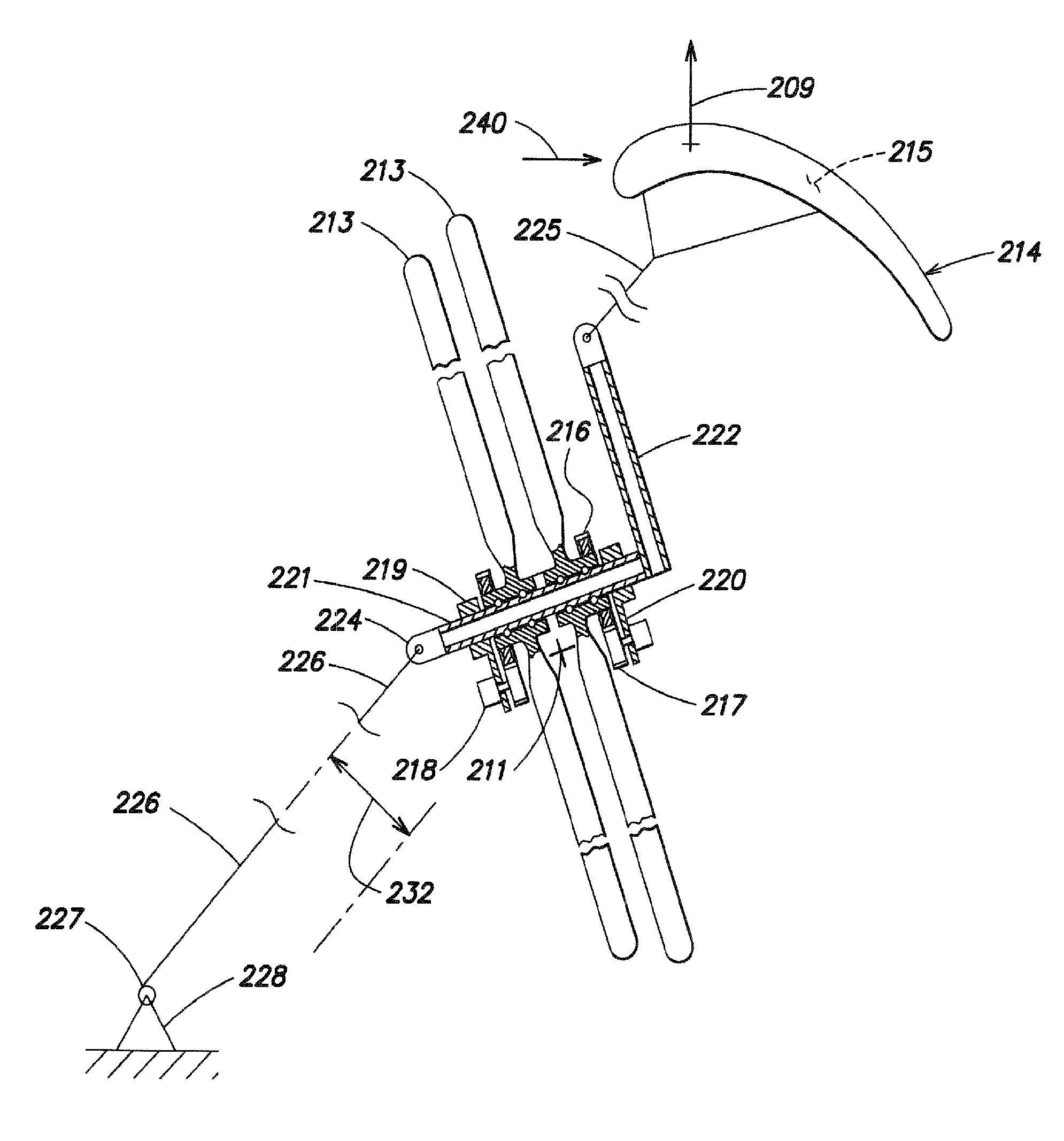
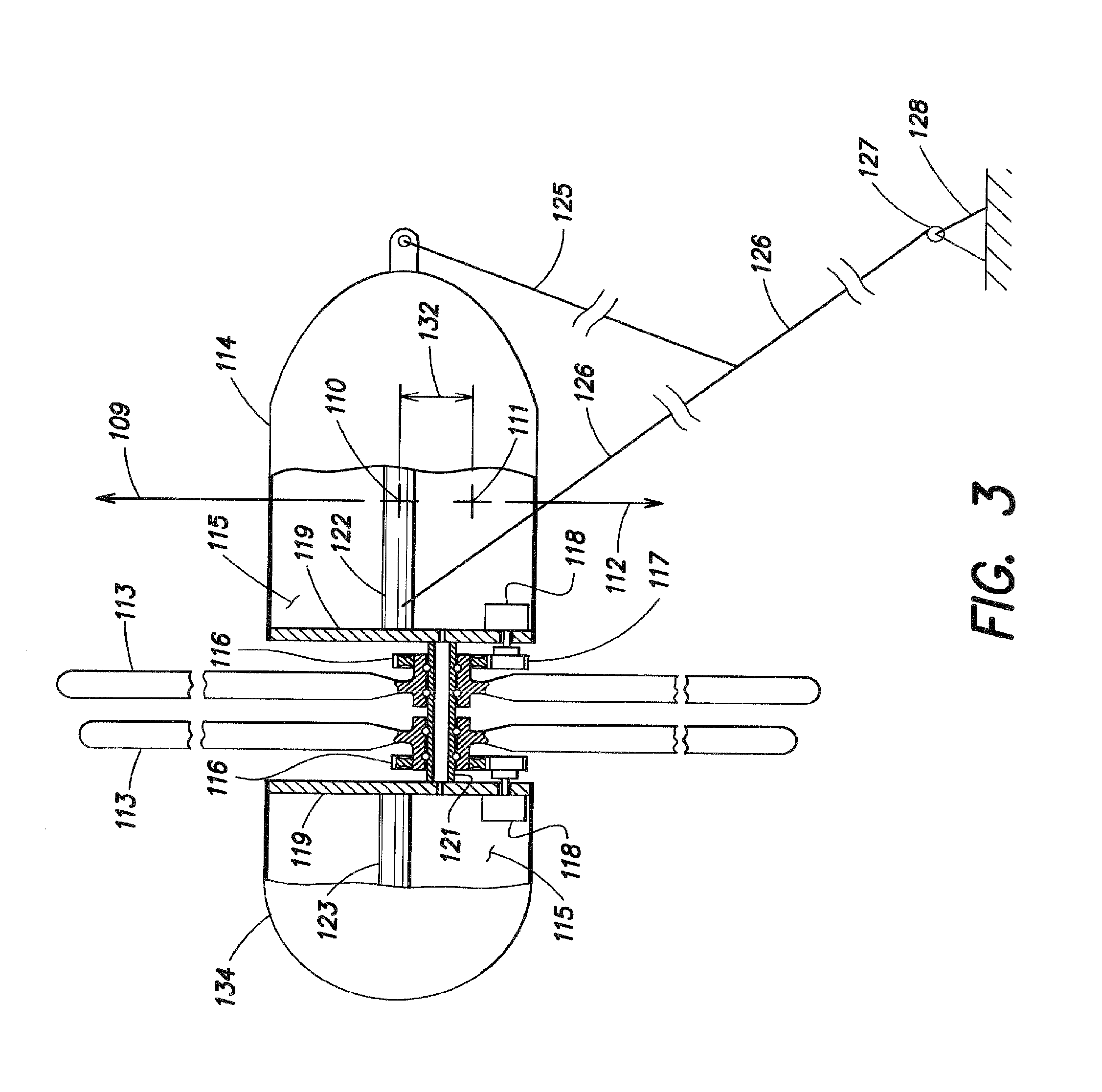
[0041]The system has two similar bodies 19, one of them is not showing in the drawings. The two bodies 19 are lighter than air and are generating a lift force 14 (14=L) which caused the system to be airborne in the atmosphere. The two bodies 19 are connected to each other rigidly by a shaft 12; the shaft 12 is placed below the symmetrical center of the two 19 bodies; a wind turbine 13 is rotatably mounted to the shaft 12, in a way that allow the turbine 13 to rotate relative to the shaft 12. The turbine 13 is connected through transmission to a generator, (the...


PUM


Abstract

An airborne system for producing electricity from wind energy includes a shaft, wind turbines rotatably mounted to the shaft and arranged to rotate independently in opposite directions when subjected to the same wind, and generators arranged to convert rotation of the turbines into electricity. A lifting section includes combination of kites and lighter than air balloons, generating a lifting force that caused the system being airborne at desire altitude. The center of gravity of the system is lower than the center of lift of the system; when the turbines of the system exposed to wind and start to rotate, torques are inducing on the shaft of the system; these torques are balancing each other and the remaining deferential torque being balanced by returning torque that is generated by the angular deviation of the center of gravity from it's lowest position, the magnitude of this returning torque, increasing as the angular deviation increased, until the system reach angular stability; electricity is generating and conducted through tether to an anchoring section for usage.

Description

FIELD OF THE INVENTION[0001]The present invention relates generally to a wind turbine system for generating electricity and more specifically to a wind turbine system for generating electricity which is air borne, and includes both turbine and generator on a common, airborne structure.BACKGROUND OF THE INVENTION[0002]Wind energy is one of the most readily available forms of renewable energy, which include solar, hydro, geothermal energy, and is therefore often used to generate electricity. The density of wind energy, in terms of watts per square meter, is one of the highest among other forms of renewable energy.[0003]Existing systems for utilizing wind energy to generate electricity have certain disadvantages. For example, since wind velocity generally increases with altitude and a large wind velocity is critical to optimize wind-based electricity generation, tall towers must be constructed to elevate a wind turbine to a high operational altitude in order to maximize the potential t...

Claims


Application Information

Patent Timeline
Patent Type & Authority Patents(United States)
IPC IPC(8): F03D9/00H02P9/04
CPCF03D1/025F03D11/04F05B2240/40Y02E10/728F05B2240/921F05B2240/922Y02E10/725F05B2240/917F03D9/11F03D9/25F03D13/20F03D80/70Y02E10/72Y02E70/30
Inventor MELLER, MOSHE
Owner MELLER MOSHE
Why Eureka
Try Eureka