Validating the error map of CMM using calibrated probe

a technology of error map and calibration probe, which is applied in the direction of mechanical measurement arrangement, instruments, using mechanical means, etc., can solve the problems of time-consuming and costly, and the movement of ball bars or other calibration artifacts around the measuring envelope of the cmm,

Active Publication Date: 2010-05-11
HEXAGON TECH CENT GMBH
View PDF14 Cites 75 Cited by
  • Summary
  • Abstract
  • Description
  • Claims
  • Application Information

AI Technical Summary

Problems solved by technology

As is well known, manual CMMs have different configurations because of the lack of drive motors.
However, the process of moving ball bars or other calibration artifacts around in the measuring envelope of the CMM is time consuming, and therefore costly.

Method used


Image

  • Validating the error map of CMM using calibrated probe
  • Validating the error map of CMM using calibrated probe
  • Validating the error map of CMM using calibrated probe

Examples


Embodiment Construction

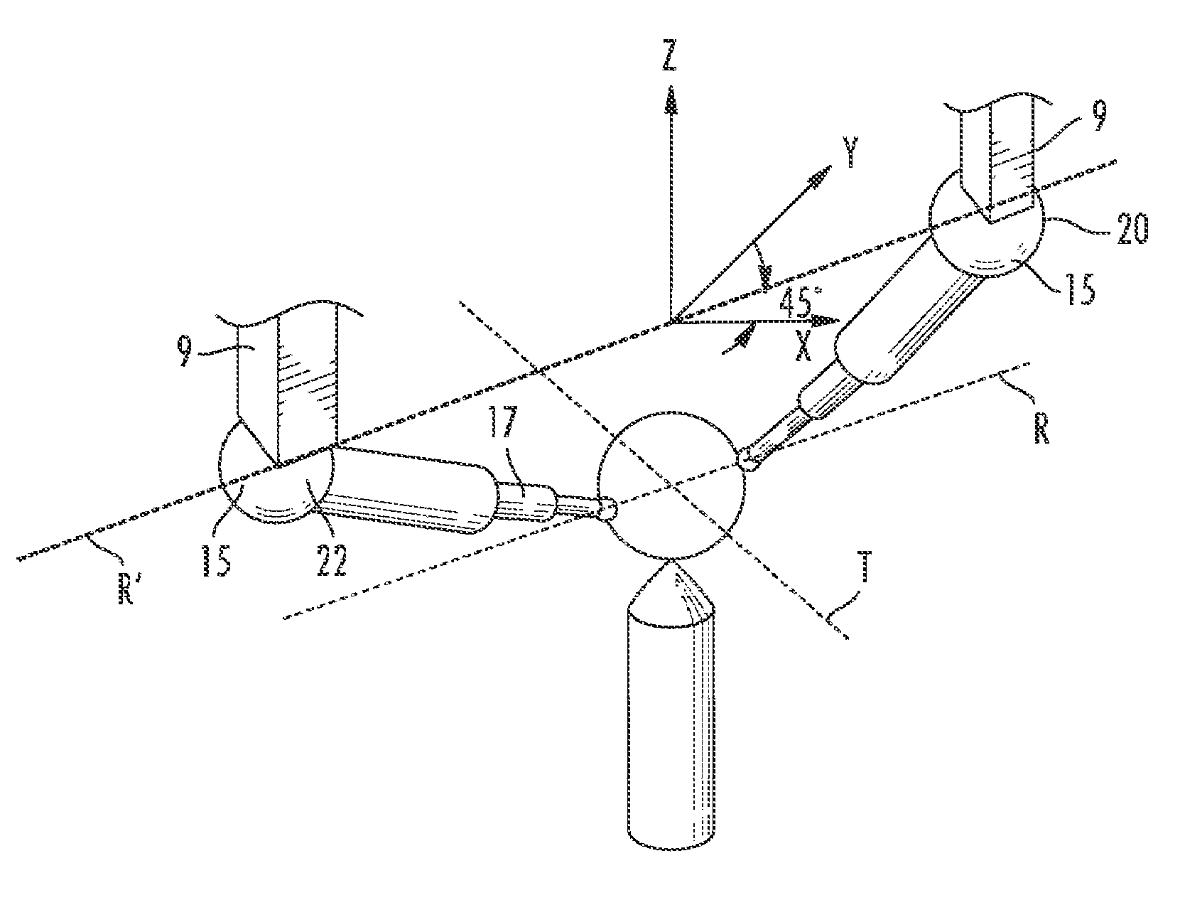
[0016]Generally speaking, the preferred embodiment involves using a calibrated, articulating probe head—which may have been calibrated according to any method known in the art, including but not limited to the methods disclosed in U.S. Pat. No. 4,888,877 or 5,665,896, each of which is hereby incorporated by reference—to validate the error map of a CMM. In the preferred embodiment, as the Z-ram 9 moves about a unitary artifact, such as a single-sphere artifact, into the various positions for the Z-ram 9 required by a calibration or error-map-validation routine, the articulating probe 15 allows the probe stylus to contact the artifact and collect a measurement. (The stylus is sometimes called a probe pin, as in U.S. Pat. No. 4,888,877.)

[0017]The articulating probe 15 for use with the preferred embodiment, shown in FIG. 4, comprises a joint and a stylus 17. (See U.S. Pat. No. 7,213,344, which is expressly incorporated herein by reference.) The articulating probe 15 has two axes of rota...


PUM


Abstract

Validating the error map of a CMM using a calibrated probe including a stylus, the probe capable of rotation about at least one axis, includes placing a calibration artifact on a table of the CMM, the table having an upper surface in an XY plane; positioning a Z-ram of the CMM in a first calibration position and a second calibration position with respect to the artifact such that the stylus contacts the artifact; calculating a measured value representing the measured length between the first and second calibration positions; calculating a nominal value based on the length of the stylus of the probe; comparing the nominal value to the measured value; and updating the error map of the CMM if the measured value differs from the nominal value by more than a predetermined value. The probe and / or the stylus moves relative to the Z-ram such that the calibration artifact remains stationary while the Z-ram is positioned in the first calibration position and the second calibration position.

Description

BACKGROUND[0001]As shown in FIG. 1, a Coordinate Measuring Machine, or CMM, comprises a measuring apparatus 2, a controller 10, and a computer 12. The measuring apparatus 2 includes a table 4 that generally extends in an XY plane, a bridge 6 spanning the table in the X direction and a carriage 8 supported on the bridge 6. The carriage 8 supports a Z-ram 9, which can move vertically, or in the Z direction. At the end of the Z-ram 9 is an articulating probe 15, such as the type disclosed in the above-referenced U.S. Pat. Nos. 7,213,344; 5,665,896 and 4,888,877.[0002]As is well known, the computer 12 and controller 10 cooperate to drive motors that move the carriage 8, bridge 6 and Z-ram 9 for the purpose of measuring work pieces situated on the table 4. Part of the articulating probe 15, generally a stylus, contacts the work piece and includes switches or sensors that trigger the computer 12 to take a measurement.[0003]The foregoing describes a direct-control CMM, meaning that the CMM...

Claims


Application Information

Patent Timeline
Patent Type & Authority Patents(United States)
IPC IPC(8): G01B5/004
CPCG01B21/045G01B21/042
Inventor HICKS, PETER
Owner HEXAGON TECH CENT GMBH
Why Eureka
Try Eureka