Sheet conveyer device and image forming apparatus with error judging system

a conveyer device and image forming technology, applied in the direction of transportation and packaging, thin material processing, article separation, etc., can solve the problems of difficult preventing the reverse conveyance of the once discharged recording sheet, the height difference is small, and the probability of reverse conveyance upon sheet feeding

Active Publication Date: 2010-05-25
BROTHER KOGYO KK
View PDF9 Cites 14 Cited by
  • Summary
  • Abstract
  • Description
  • Claims
  • Application Information

AI Technical Summary

Benefits of technology

[0010]In view of the above drawbacks, the present invention is advantageous in that a sheet conveyer device capable of preventing a reversely conveyed sheet from interfering a next feeding operation, which is resumed after a sheet feeding error, and an image forming apparatus having the sheet conveyer device are provided.
[0014]According to the above configuration, the feeding operation resumed after the feeding error can be performed without being interrupted by the sheet which was left in the conveyer path. Therefore, an image can be effectively formed on the sheet which is fed in the resumed feeding operation.

Problems solved by technology

Occasionally, the image forming apparatus may be obliged to have a small height difference between a top level of the discharge tray and a level of the discharge roller pair due to a volume limitation of the image forming apparatus, specifically when the entire image forming apparatus is configured to be small in height.
When the rear end of the previously discharged recording sheet is thus close to the discharge roller pair, preventing the reverse conveyance of the once discharged recording sheet is yet difficult, even with the sheet sweeping rotary body provided to the driving roller of the discharge roller pair.
Specifically, it is to be noted that the reverse conveyance is likely to occur upon a sheet feeding error, for example, in which the feeder roller slips on the topmost recording sheet stacked in the sheet feed tray, and in which the recording sheet is jammed in the sheet conveyer path.
When the feeding operation resumes after an error cause is removed, the recording sheet left in the sheet conveyer path may be reversed toward the upstream side further from the conveyer rollers and interfere a next feeding operation.
Additionally, when the reverse conveyance occurs in a scanner device having an ADF (auto document feeder), and a once discharged original document is withdrawn in a sheet conveyer path according to reverse registering of the original documents, a next original document to be scanned may be interfered with the reversed document in the sheet conveyer path, and an image on the next original document may not be scanned correctly.

Method used


Image

  • Sheet conveyer device and image forming apparatus with error judging system
  • Sheet conveyer device and image forming apparatus with error judging system
  • Sheet conveyer device and image forming apparatus with error judging system

Examples


Embodiment Construction

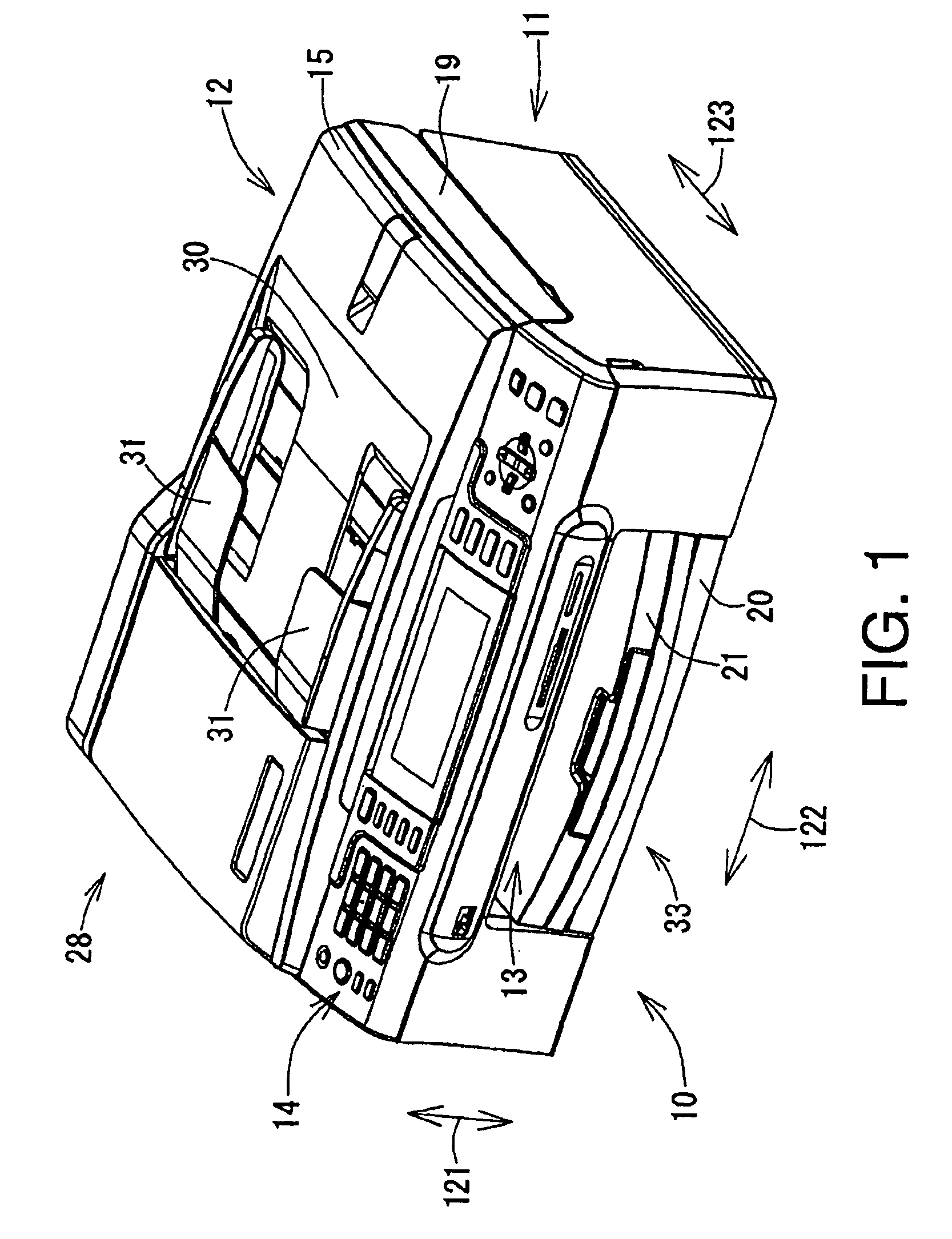
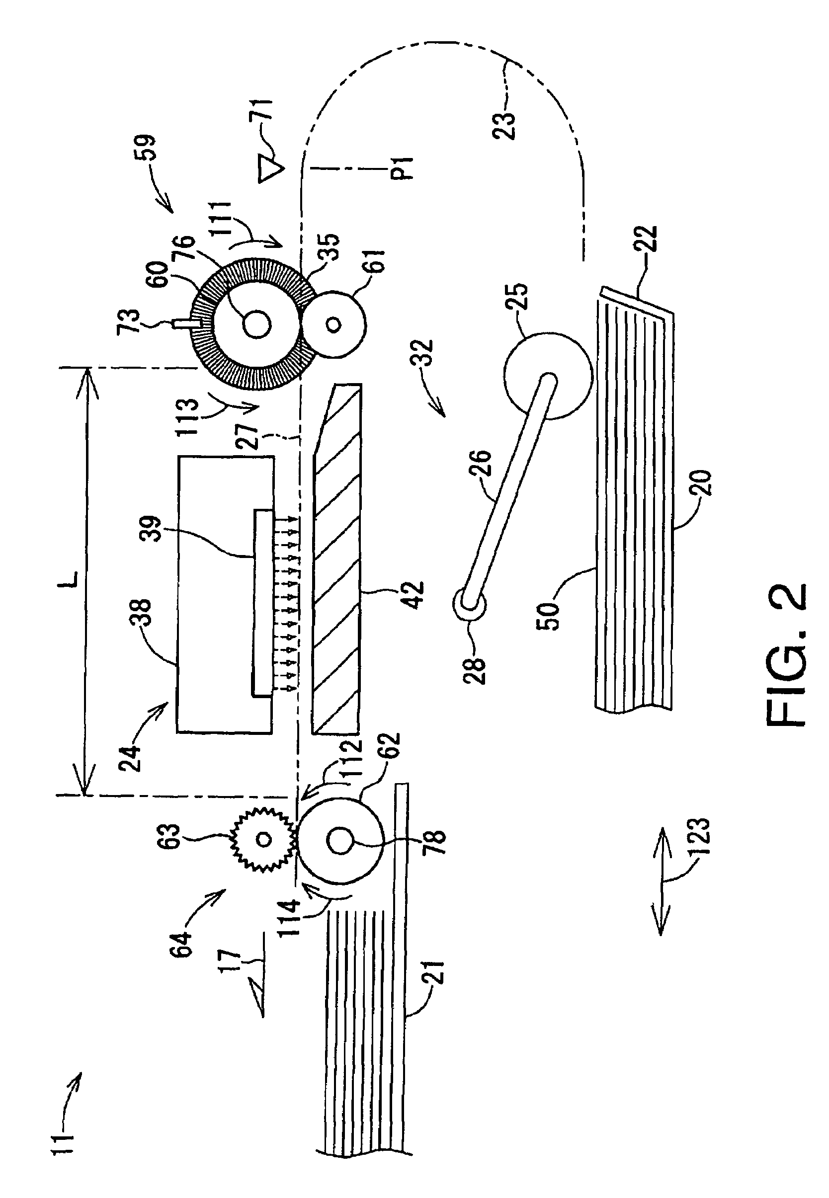
[0022]Hereinafter, embodiments according to the present invention will be described with reference to the accompanying drawings. FIG. 1 illustrates an external and perspective view of the MFD 10 according to the embodiment of the present invention. FIG. 2 illustrates an internal configuration of a printer unit 11 of the MFD 10 according to the embodiment of the present invention, although a part of a feed tray 20 and a part of a discharge tray 21 are omitted and not shown. First, an overall configuration of an MFD 10 according to the embodiment of the present invention will be described.

[0023]The MFD 10 according to the present embodiment is configured integrally with a printer unit 11 and a scanner unit 12 and provided with functionalities for printing, scanning, and facsimile transmission. However, the MFD 10 may not necessarily be equipped with the scanner unit 12, but the MFD 10 may be replaced with a printer device having solely a printing function.

[0024]A body of the MFD 10 ac...


PUM


Abstract

A sheet conveyer device to convey a sheet in a conveyer path, including a first roller pair arranged in an intermediate position in the conveyer path, a feeder to feed the sheet toward the first roller pair during a feeding operation, a discharge portion, on which the sheet is discharged, a second roller pair arranged in the conveyer path in a position closer to the discharge portion than the first roller pair, a control unit to control the first and the second roller pairs to rotate synchronously, and a judging system to judge whether a sheet feeding error has occurred in the feeder, is provided. The control unit controls the first and the second roller pairs to rotate synchronously in a second direction during the feeding operation and in a first direction when the judging system judges that the sheet feeding error has occurred during the feeding operation.

Description

CROSS REFERENCE TO RELATED APPLICATION[0001]This application claims priority from Japanese Patent Application No. 2008-100859 filed on Apr. 8, 2008, the entire subject matter of which is incorporated herein by reference.BACKGROUND[0002]1. Technical Field[0003]Aspects of the present invention relate to a sheet conveyer device having a pair of discharge rollers, which nip a sheet therebetween and rotate to discharge the sheet out of a conveyer path, and an image forming apparatus having the sheet conveyer device.[0004]2. Related Art[0005]When an instruction for forming an image on a recording sheet is entered in an image forming apparatus (e.g., an inkjet printer), a feeder roller being pressed onto a surface of the recording sheet, which is stored in a sheet feed tray, rotates to direct the sheet into the sheet conveyer path. Along the sheet conveyer path in the image forming apparatus, several components for forming images are installed. Specifically, recording heads to record image...

Claims


Application Information

Patent Timeline
Patent Type & Authority Patents(United States)
IPC IPC(8): B65H5/00
CPCB65H5/062B65H7/02B65H2511/24B65H2511/514B65H2513/41B65H2701/1311B65H2513/52B65H2220/03B65H2220/02B65H2220/01
Inventor HIRATE, KENSUKEMIZUTANI, SHUNSUKE
Owner BROTHER KOGYO KK
Why Eureka
Try Eureka