Internal combustion engine system and control method of internal combustion engine system

a technology of internal combustion engine and control method, which is applied in the direction of electric control, machines/engines, mechanical equipment, etc., can solve the problems of low engine water temperature but high catalyst temperature, affecting the operation of egr, so as to prevent a temperature increase of purification catalyst, improve the combustion state of the engine, and reduce the temperature of the exhaust gas

Inactive Publication Date: 2011-05-03
TOYOTA JIDOSHA KK
View PDF7 Cites 6 Cited by
  • Summary
  • Abstract
  • Description
  • Claims
  • Application Information

AI Technical Summary

Benefits of technology

[0005]The EGR device is not restrictively used to prevent the excessive increase of the engine temperature (engine water temperature), but is also applicable to lower the temperature of the exhaust gas and thereby prevent a temperature increase of a purification catalyst provided in an exhaust line of the engine. The low engine temperature condition generally worsens the combustion state in the engine and interferes with the EGR operation. The driver's heavy depression of an accelerator pedal to a significant depth immediately after a start of the engine in the cold state triggers an abrupt increase of the catalyst temperature and causes the state of low engine water temperature but high catalyst temperature. In this state, the EGR operation is not allowable, so that the catalyst temperature increases to an undesirably high level. One proposed measure for preventing the increase of the catalyst temperature consistently performs fuel amount increase control, in place of the EGR control, in the condition of the high catalyst temperature. The fuel amount increase control increases the amount of fuel to be injected from a fuel injection valve and utilizes the latent heat of vaporization in the increased amount of the fuel to cool down the purification catalyst. The increased amount of fuel injection, however, undesirably worsens the fuel consumption.
[0006]An object of the present invention is to provide an internal combustion engine system and the control method of the internal combustion engine system that prevent overheat of a purification catalyst while minimizing the deterioration of fuel consumption.
[0009]Upon satisfaction of the preset condition for preventing the temperature increase of the purification catalyst, when the temperature of the internal combustion engine is not lower than the preset reference temperature, the internal combustion engine system of this aspect of the invention performs the first control of controlling the exhaust recirculation module to recirculate the part of the exhaust of the internal combustion engine into the gas intake line and thereby prevent the temperature increase of the purification catalyst. When the temperature of the internal combustion engine is lower than the preset reference temperature, on the other hand, the internal combustion engine system performs the second control of controlling the fuel injection module to increment the amount of the fuel to be injected into the internal combustion engine and thereby prevent the temperature increase of the purification catalyst. This arrangement effectively prevents overheat of the purification catalyst while minimizing the fuel consumption for controlling the temperature increase of the purification catalyst.
[0010]In the internal combustion engine system of the invention, the temperature increase controller may continue the second control without abruptly stopping even when the temperature of the internal combustion engine represented by the measured temperature-reflecting physical quantity increases from a level of lower than the preset reference temperature to a level of not lower than the preset reference temperature during execution of the second control. This arrangement effectively prevents the state of the engine from becoming unstable by an abrupt switchover between the first and the second control.
[0016]Upon satisfaction of the preset condition for preventing the temperature increase of the purification catalyst, when the temperature of the internal combustion engine is not lower than the preset reference temperature, the control method of this aspect of the invention performs the first control of controlling the exhaust recirculation module to recirculate the part of the exhaust of the internal combustion engine into the gas intake line and thereby prevent the temperature increase of the purification catalyst. When the temperature of the internal combustion engine is lower than the preset reference temperature, on the other hand, the control method performs the second control of controlling the fuel injection module to increment the amount of the fuel to be injected into the internal combustion engine and thereby prevent the temperature increase of the purification catalyst. This arrangement effectively prevents overheat of the purification catalyst while minimizing the fuel consumption for controlling the temperature increase of the purification catalyst.
[0017]In the control method of the invention, the step may continue the second control without abruptly stopping even when the temperature of the internal combustion engine represented by the measured temperature-reflecting physical quantity increases from a level of lower than the preset reference temperature to a level of not lower than the preset reference temperature during execution of the second control. This arrangement effectively prevents the state of the engine from becoming unstable by an abrupt switchover between the first and the second control.

Problems solved by technology

The low engine temperature condition generally worsens the combustion state in the engine and interferes with the EGR operation.
The driver's heavy depression of an accelerator pedal to a significant depth immediately after a start of the engine in the cold state triggers an abrupt increase of the catalyst temperature and causes the state of low engine water temperature but high catalyst temperature.
In this state, the EGR operation is not allowable, so that the catalyst temperature increases to an undesirably high level.
The increased amount of fuel injection, however, undesirably worsens the fuel consumption.

Method used


Image

  • Internal combustion engine system and control method of internal combustion engine system
  • Internal combustion engine system and control method of internal combustion engine system
  • Internal combustion engine system and control method of internal combustion engine system

Examples


Embodiment Construction

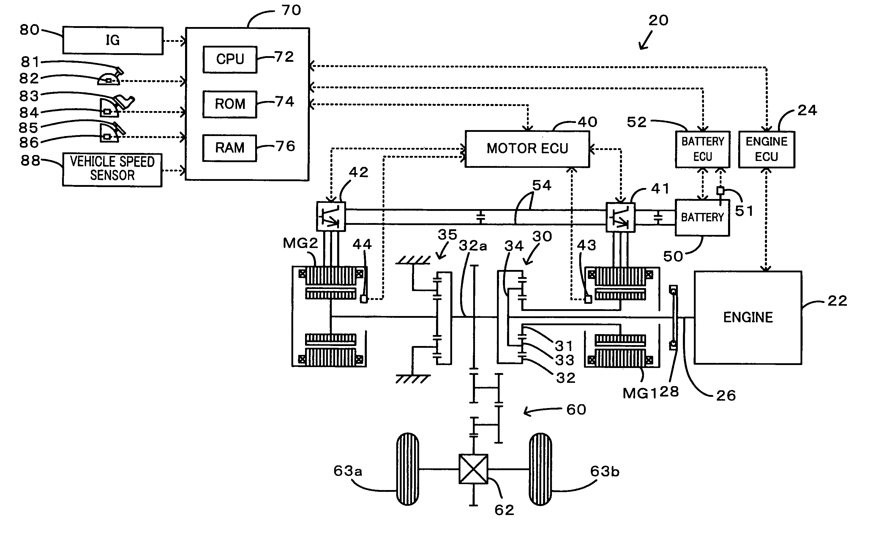
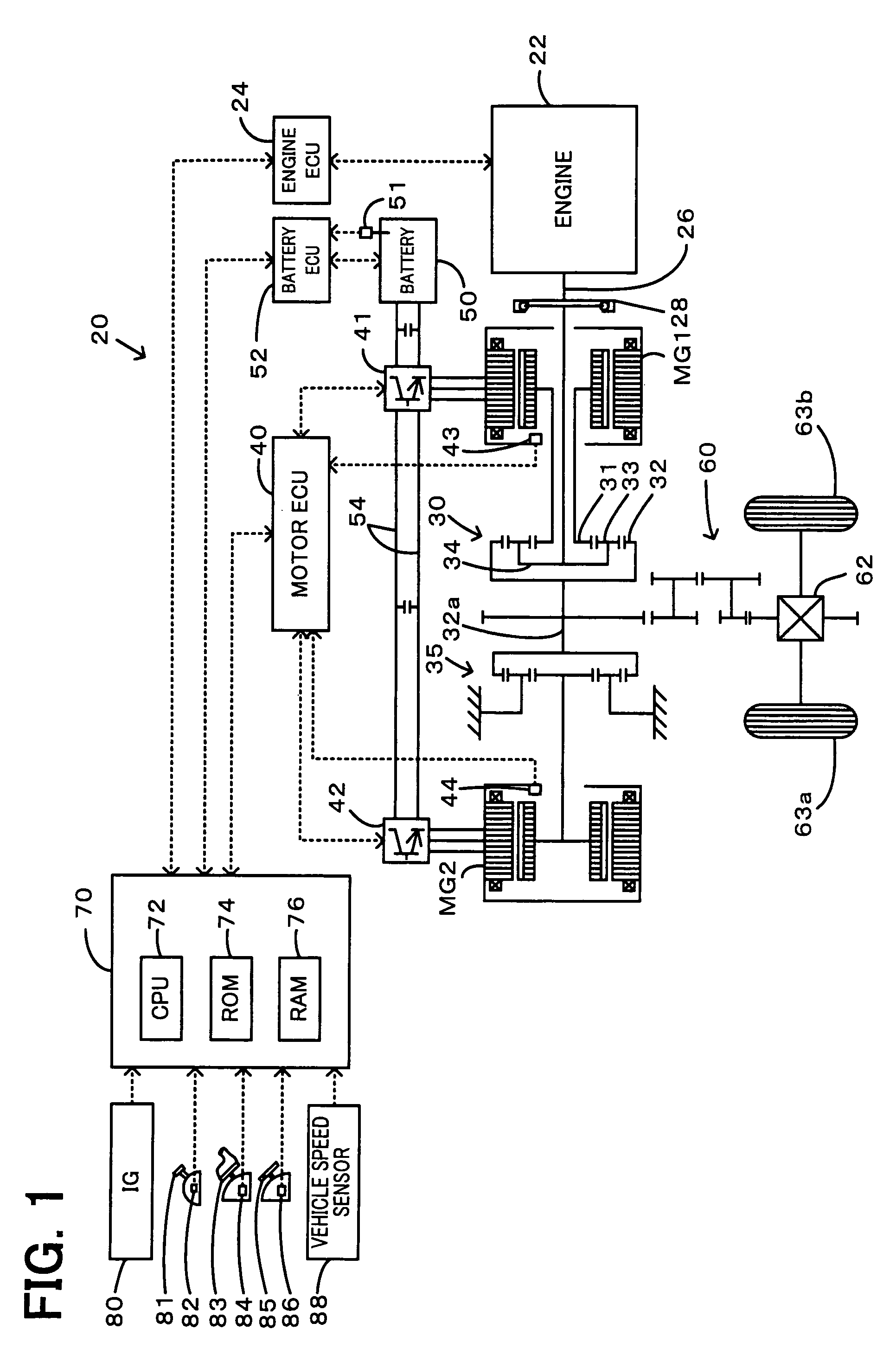
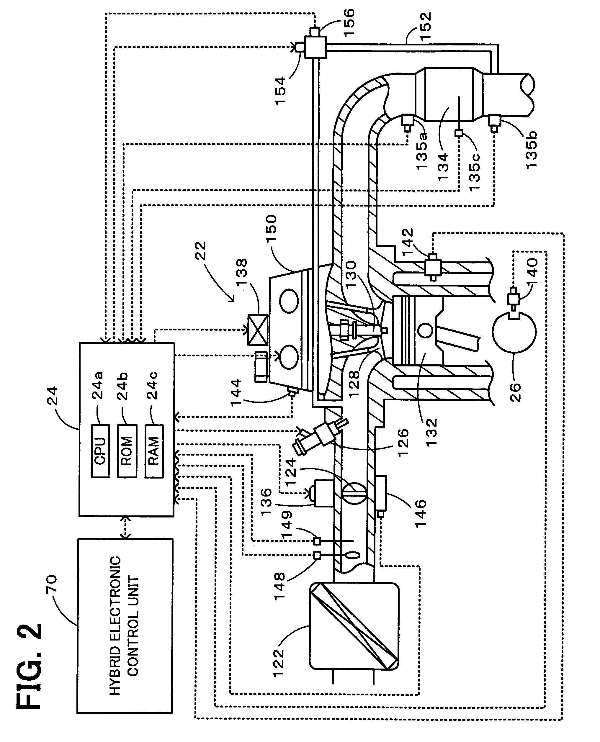
[0028]FIG. 1 schematically illustrates the configuration of a hybrid vehicle 20 equipped with an internal combustion engine system incorporated in a power output apparatus in one embodiment of the invention. FIG. 2 is a schematic view showing the structure of an engine 22. As illustrated, the hybrid vehicle 20 of the embodiment includes the engine 22, a three shaft-type power distribution integration mechanism 30 connected via a damper 28 to a crankshaft 26 or an output shaft of the engine 22, a motor MG1 connected to the power distribution integration mechanism 30 and designed to have power generation capability, a reduction gear 35 attached to a ring gear shaft 32a or a driveshaft linked with the power distribution integration mechanism 30, a motor MG2 connected to the reduction gear 35, and a hybrid electronic control unit 70 configured to control the operations of the whole hybrid vehicle 20. The engine 22 and an engine electronic control unit 24 configured to control the operat...


PUM


Abstract

Under the condition that a catalyst temperature Tc of a purification catalyst reaches or exceeds a preset reference temperature Tcref, when a cooling water temperature Tw of an engine is not lower than a preset reference temperature Twref, the internal combustion engine system of the invention sets a target exhaust recirculation rate EGR* based on a given rotation speed Ne of the engine and a given load factor KL and performs exhaust recirculation control to open an EGR valve at a specific angle or opening corresponding to the set target exhaust recirculation rate EGR*. When the cooling water temperature Tw is lower than the preset reference temperature Twref, on the other hand, the internal combustion engine system of the invention sets a fuel increment amount α based on the given rotation speed Ne of the engine and the given load factor KL and performs fuel increment control to increase the specific amount of fuel, which is set relative to the amount of intake air to attain the stoichiometric air-fuel ratio as a value to be injected from a fuel injection valve, by the set fuel increment amount α. This arrangement effectively prevents overheat of the purification catalyst while minimizing the deterioration of fuel consumption.

Description

BACKGROUND ART[0001]1. Technical Field[0002]The present invention relates to an internal combustion engine system including an internal combustion engine with a purification catalyst provided in an exhaust line thereof, a fuel injection module configured to inject a fuel into the internal combustion engine, an exhaust recirculation module arranged to recirculate part of exhaust of the internal combustion engine into a gas intake line of the internal combustion engine, and a temperature-reflecting physical quantity detector constructed to measure a temperature-reflecting physical quantity representing temperature of the internal combustion engine, and a control method of the internal combustion engine system.[0003]2. Related Art[0004]One proposed structure of an internal combustion engine system is equipped with an EGR (exhaust gas recirculation) device designed to recirculate the exhaust gas into a gas intake line (see, for example, Patent Document 1). The EGR device mounted on the ...

Claims


Application Information

Patent Timeline
Patent Type & Authority Patents(United States)
IPC IPC(8): F01N3/00
CPCF02D29/02F02D41/005F02D41/0235Y02T10/47F02D2041/0265Y02T10/40
Inventor SUGIMOTO, HITOKI
Owner TOYOTA JIDOSHA KK
Why Eureka
Try Eureka