Injection molding apparatus having magnetic valve pin coupling

a technology of injection molding apparatus and valve pin, which is applied in the field of injection molding apparatus, can solve the problems of injection molding apparatus shutting down for maintenance or repair, and molded product defects,

Active Publication Date: 2010-05-25
MOLD MASTERS 2007
View PDF20 Cites 34 Cited by
  • Summary
  • Abstract
  • Description
  • Claims
  • Application Information

AI Technical Summary

Problems solved by technology

When a cavity, valve pin, heater, mold gate, or other related component wears or fails, the molded product may have defects and the injection molding apparatus may have to be shut down for maintenance or repair.

Method used


Image

  • Injection molding apparatus having magnetic valve pin coupling
  • Injection molding apparatus having magnetic valve pin coupling
  • Injection molding apparatus having magnetic valve pin coupling

Examples


Embodiment Construction

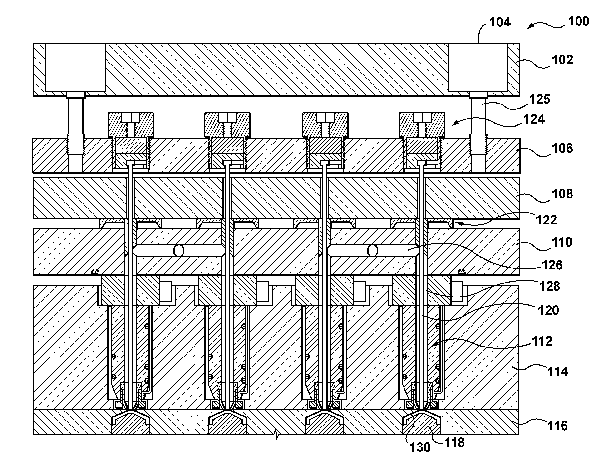
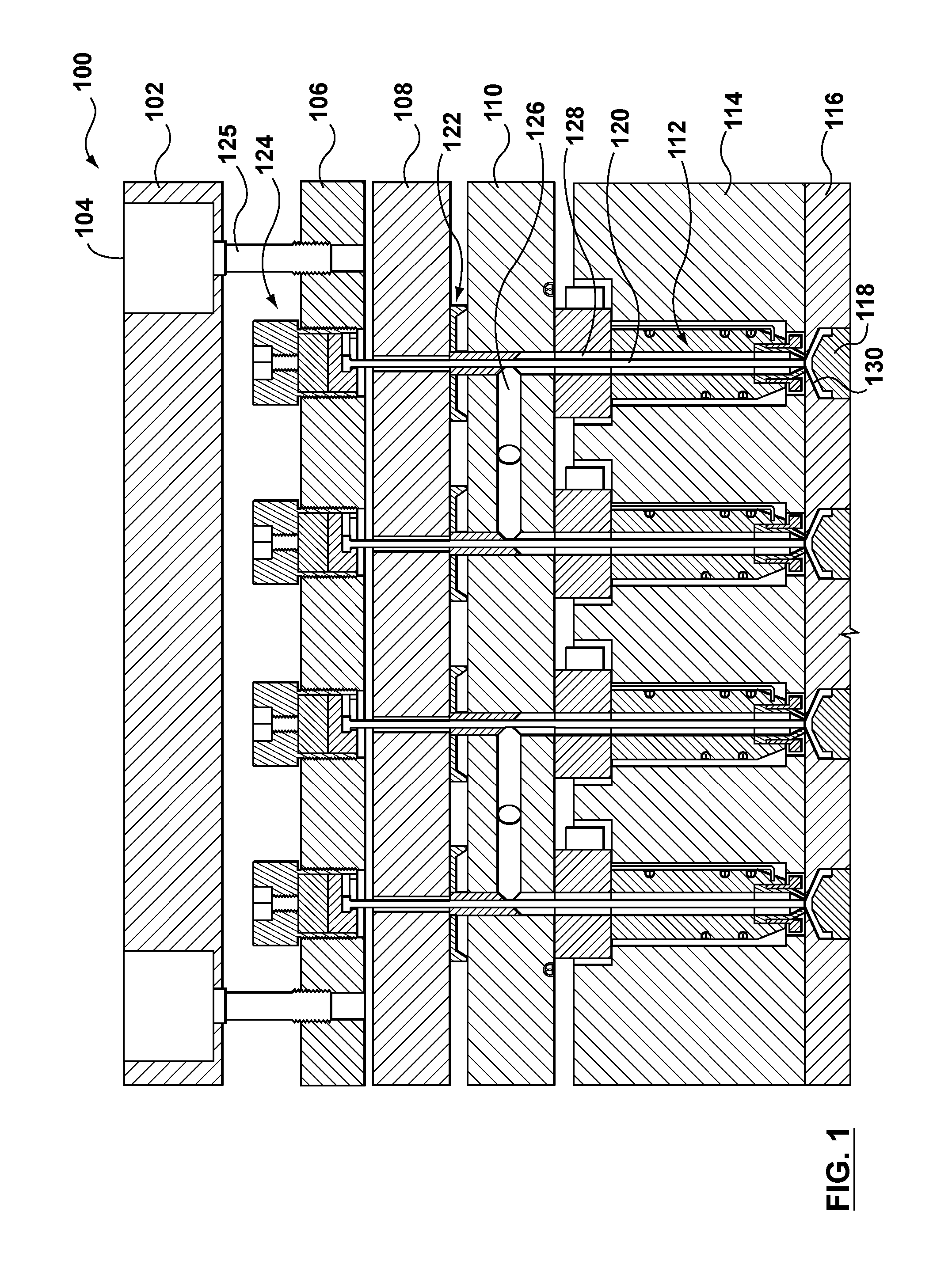
[0024]FIG. 1 shows an injection molding apparatus 100 according to an embodiment of the present invention. The features and aspects described for the other embodiments can be used accordingly with the present embodiment.

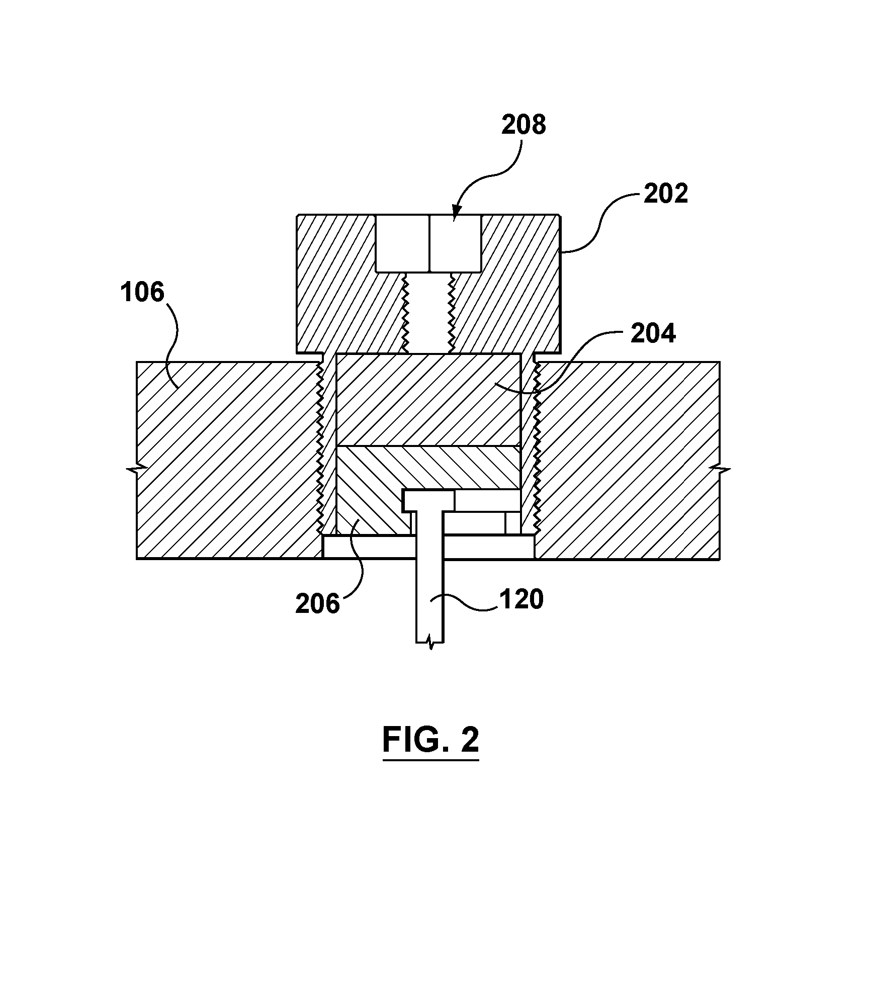
[0025]The injection molding apparatus includes an actuator plate 102, actuators 104, a valve pin plate 106, a back plate 108, a manifold 110, nozzles 112, a mold plate 114, a cavity plate 116, cores 118, valve pins 120, valve pin bushings 122, and magnetic couplings 124. The injection molding apparatus 100 can include any number of manifolds and nozzles, in any configuration. In this embodiment, one manifold is shown for simplicity. The injection molding apparatus 100 can include additional components, such as mold plates, alignment dowels, mold gate inserts, and cooling channels, among others.

[0026]The actuator plate 102 has openings for accommodating the actuators 104. If the actuators 104 depend on a working fluid for operation (i.e., pneumatic or hydraulic types)...


PUM

PropertyMeasurementUnit
magneticaaaaaaaaaa
magnetic forceaaaaaaaaaa
attractive magnetic forceaaaaaaaaaa

Abstract

A magnetic coupling for an injection molding apparatus, such as a hot half or hot runner, includes a first magnetic part for connection to an actuator, a valve pin plate, or the like and a movable second magnetic part for connection to a valve pin. The first magnetic part and the second magnetic part are coupled by a magnetic force. The first magnetic part can be part of the actuator. The second magnetic part can be part of the valve pin. A valve pin plate can be provided for a plurality of valve pins.

Description

BACKGROUND OF THE INVENTION[0001]1. Field of the Invention[0002]This invention is relates to an injection molding apparatus, and more particularly, an injection molding apparatus having a valve pin.[0003]2. Related Art[0004]Injection molding apparatuses, such as hot halves and hot runners, commonly use valve pins to control flow of molding material.[0005]When a cavity, valve pin, heater, mold gate, or other related component wears or fails, the molded product may have defects and the injection molding apparatus may have to be shut down for maintenance or repair. Such downtime eats into production time, which is nearly always sought to be maximized.SUMMARY OF THE INVENTION[0006]A magnetic coupling for an injection molding apparatus, such as a hot half or hot runner, includes a first magnetic part for connection to an actuator, a valve pin plate, or the like and a movable second magnetic part for connection to a valve pin. The first magnetic part and the second magnetic part are coupl...

Claims


Application Information

Patent Timeline
Patent Type & Authority Patents(United States)
IPC IPC(8): B29C45/23
CPCB29C45/281Y10T29/49815B29C2045/2813
Inventor FEICK, MURRAYFAIRY, FABRICEENGLEDER, STEFANURSU, DOUGLAS
Owner MOLD MASTERS 2007
Why Eureka
Try Eureka