Eureka AIR delivers breakthrough ideas for toughest innovation challenges, trusted by R&D personnel around the world.

Method and device for optical fiber connection

a technology of optical fiber and connection method, applied in the field of optical communication, can solve the problems of limiting factors, achieving high transmission rates, and relatively narrow bandwidth of electric cables

Inactive Publication Date: 2010-05-25
PIRELLI & C
View PDF21 Cites 0 Cited by
  • Summary
  • Abstract
  • Description
  • Claims
  • Application Information

AI Technical Summary

Benefits of technology

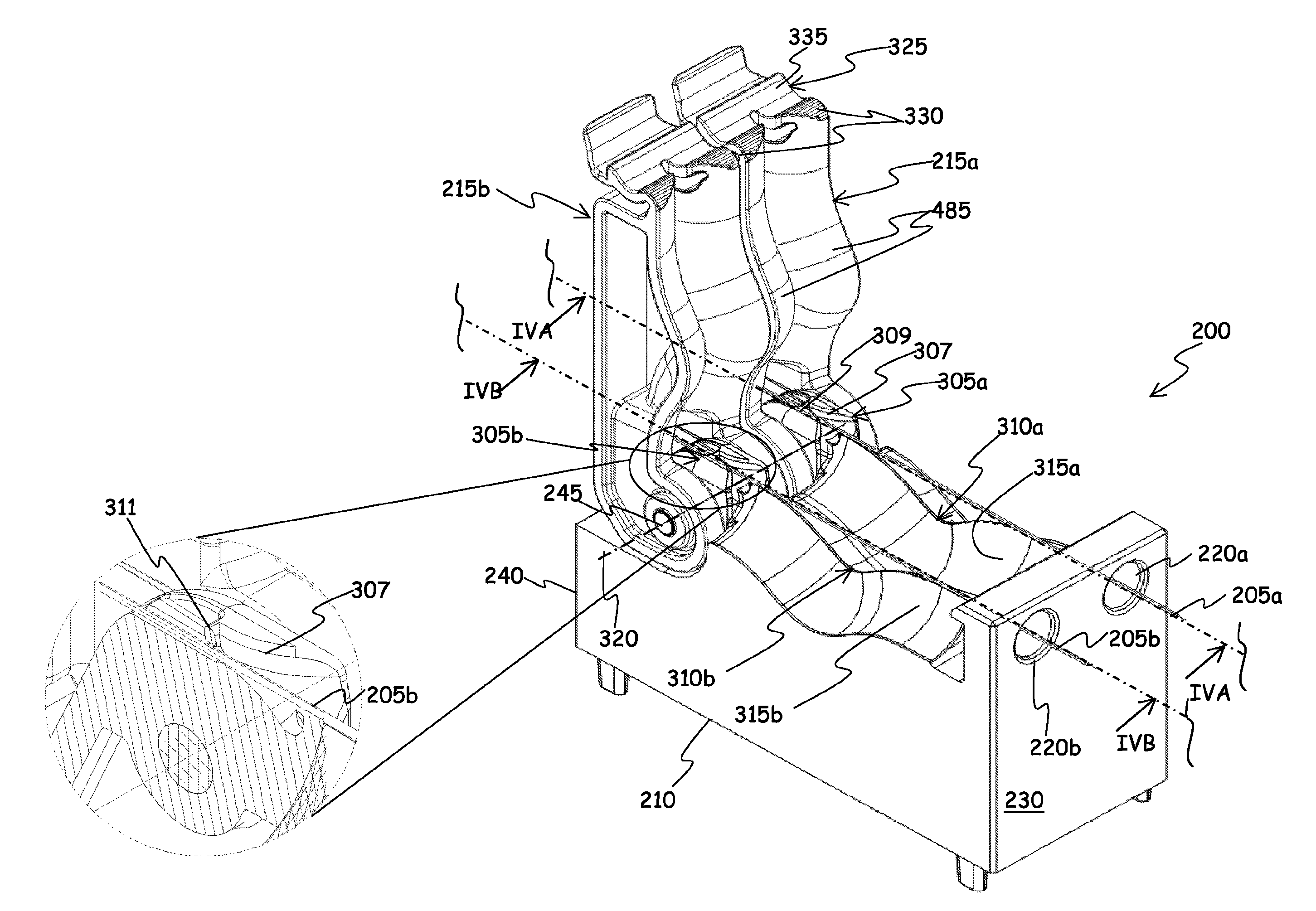
[0016]The Applicant has found that such a problem can be solved by using a technique that allows an optical signal to be extracted / injected from / into an optical fiber without the need of “connectorizing” the optical fiber, or of making a fused junction, but through suitable bending of the optical fiber.
[0017]Indeed, the Applicant has observed that with this technique the optical fiber terminations can be accomplished leaving the fibers complete of their protective coating (provided that the same is sufficiently transparent). Differently from the use of connectors or fused junctions, when using fiber bending the terminal face of the optical fiber has no particular optical function, so the aforementioned critical operations of stripping, cleaving and polishing of the fiber, required by the use of optical connectors or fused junctions, are eliminated.
[0023]In particular, the Applicant observes that the known coupling devices are complex, include separate parts, are bulky, and not easy to be used. In addition, they do not guarantee a high reproducibility of the fiber coupling which is needed for a high bit-rate, long reach optical system having low deployment costs.
[0026]In U.S. Pat. No. 4,759,605, the presence of the groove in the fiber bending element helps ensuring the fiber positioning. However, in that device as the bending element is brought towards the surface of the resiliently deformable material, due to inevitable irregularities of the parts surfaces, the optical fiber may get pinched in two positions at both sides of a fiber section where the light has to be extracted / injected: if this occurs, bringing the bending element closer to the resiliently deformable material surface may induce in the fiber stresses that cannot be dissipated, and the optical fiber may become corrugated in the section thereof that is expected to be optically active for the light extraction / injection, or the intimate contact of the fiber with the resiliently deformable material surface may be prevented, with the result that the efficiency of the optical coupling is greatly impaired.
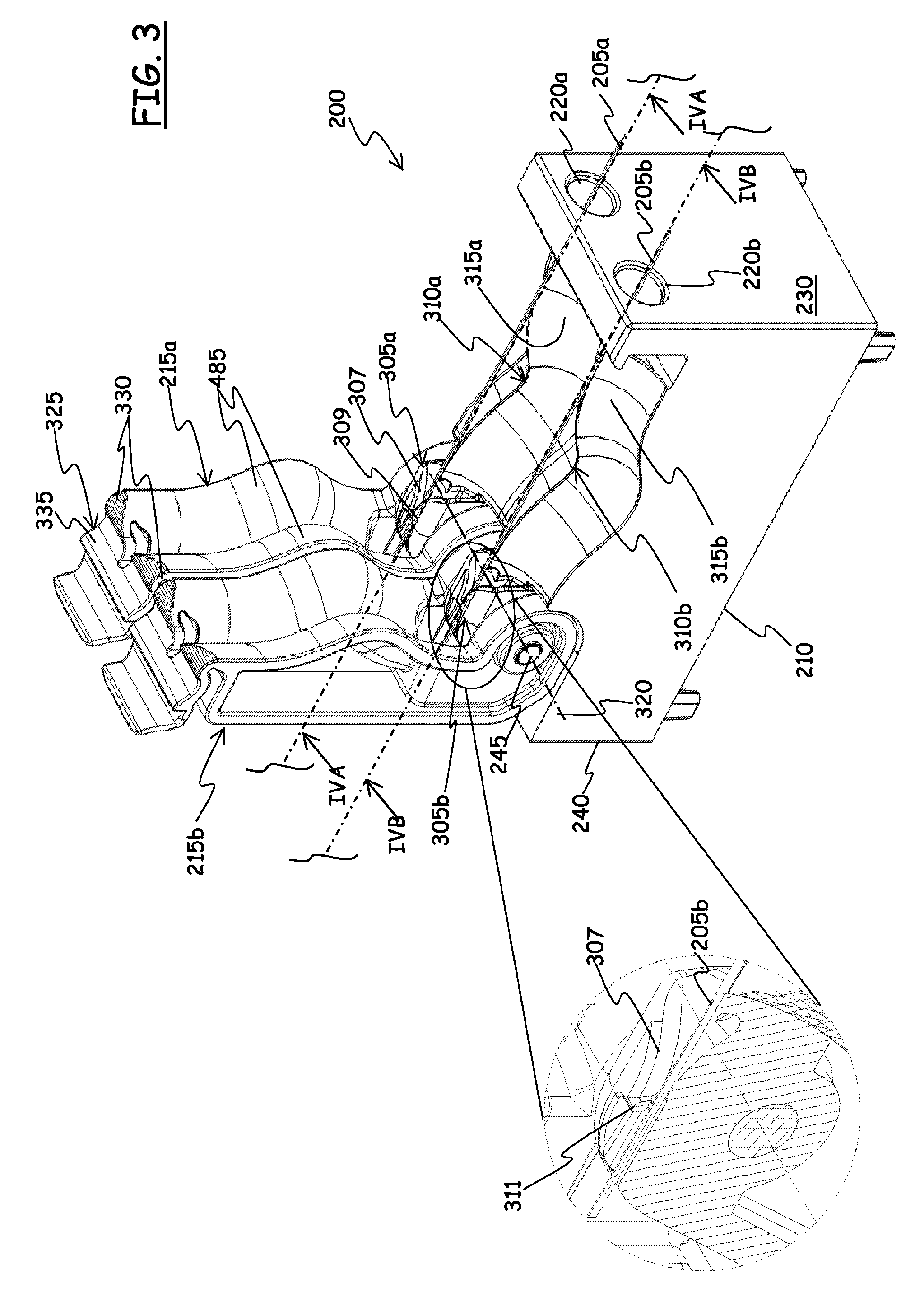
[0027]The Applicant has thus tackled the problem of providing a device that, using a suitable mechanism, is adapted to accomplish a fiber termination, ensuring a high power budget, by accommodating and keeping with high precision the fiber properly bent and in optical alignment with respect to, e.g., the opto-electronic device, and is simple to use, so that the operations of connection of the optical fiber to the opto-electronic device can be carried out by any technician, even if not specialized in optical cable terminations, or, possibly, even by the final user.

Problems solved by technology

However, electrical cables have a relatively narrow bandwidth, and are becoming a limiting factor against the achievement of high transmission rates.
Moreover, electrical cables raise problems of electromagnetic interference and impedance matching.
Furthermore, electrical cables are relatively stiff, and thus are difficult to insert into the suitable raceways of a building (which, for electrical safety requirements, are to be distinct from the raceways used for the distribution of electrical energy), and, due to their bulkiness, the number of cables that can be inserted in the raceway is limited.
However, using optical connectors and fused junctions is cumbersome and critical operations are necessary that involve fiber stripping (i.e., removal of the protective outer fiber coating), cleaving and polishing operations, which are very delicate to carry out on site, require high precision (tolerances are in the range of micrometers), and have to be executed by highly specialized personnel, using special tools.
All this increases the installation time and costs.
Moreover, it often happens that these complex operations have to be carried out in inconvenient and narrow spaces (for example, under a table or desk), increasing the risk that the optical fiber connection is not accomplished with the necessary precision, with the consequence that the link performance strongly reduces.
Therefore, despite their several advantages, the use of fiber optic cables in networks for distributing signals to a plurality of end users has up to now been highly limited both due to the high installation costs and because the optical connection may be unreliable if the aforementioned operations are not carried out correctly.

Method used


Image

  • Method and device for optical fiber connection
  • Method and device for optical fiber connection
  • Method and device for optical fiber connection

Examples


Embodiment Construction

)

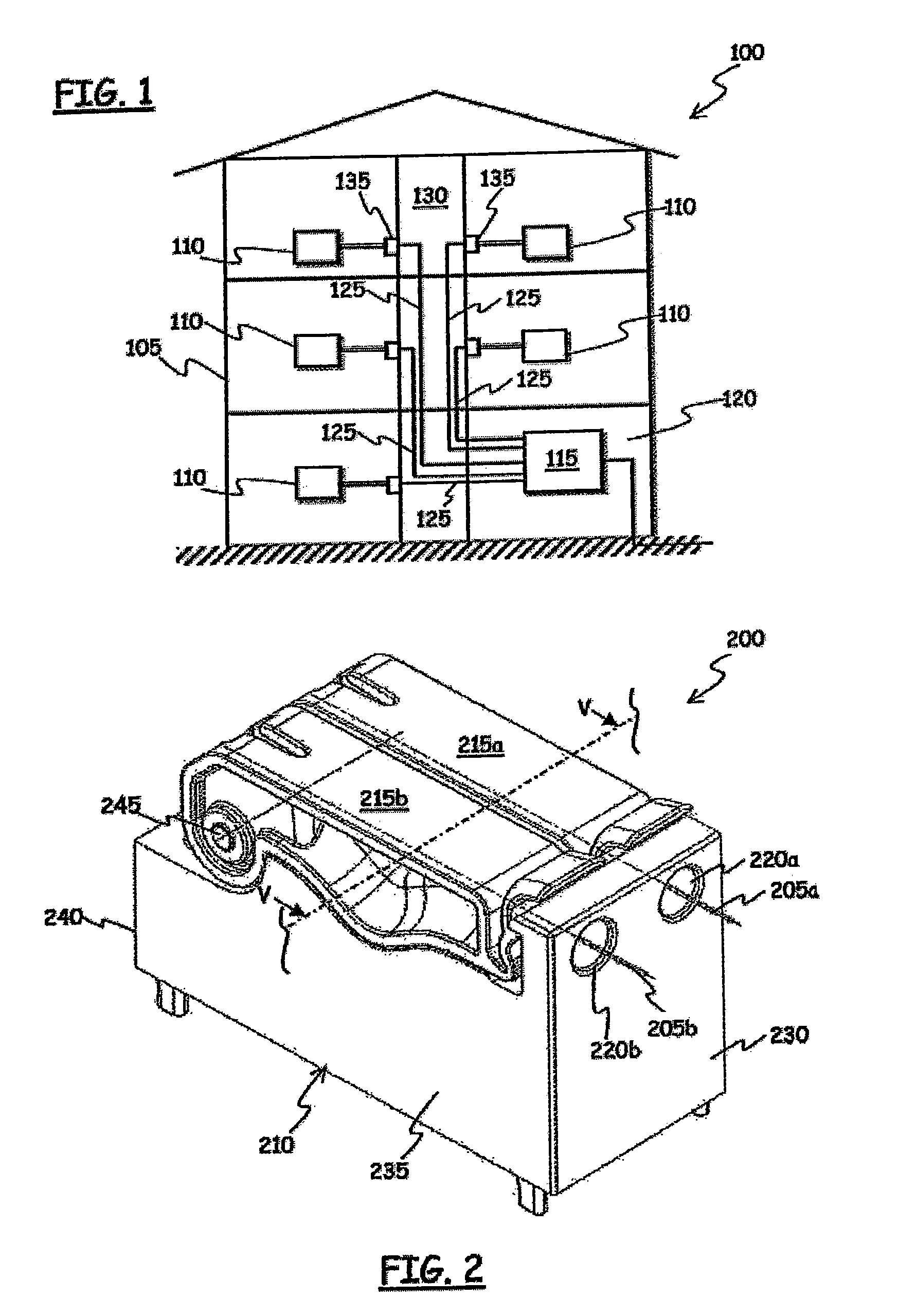
[0062]In FIG. 1 an exemplary scenario is depicted wherein a device according to an embodiment of the present invention is advantageously used. The considered scenario is that of a typical residential application, wherein a data communications network 100 brings network access to end users within a building 105. For example, the network 100 can be used to make available cable television (e.g., on-demand television), telephone, Internet and equivalent services at end users' electronic appliances 110 that can include for example television sets, personal computers, telephones or equivalent appliances.

[0063]A distribution unit 115 is arranged in a cellar or basement 120 of the building 105, and point-to-point optical cable links 125—with the respective optical cables housed in a suitable raceway 130 of the building—connect the distribution unit 115 to the user appliances 110 situated in the users' apartments at the various levels of the building.

[0064]For each of the point-to-point opt...


PUM


Abstract

A device for coupling an optical fiber includes: a first surface and a second surface, including respective active surface portions; at least one optical fiber positioning element adapted to position at least one point of an optical fiber on a longitudinally median plane of the second surface. The first and second surfaces are movable relative to one another between a first and a second relative position, and, when in the second relative position, cooperate to accommodate a section of the optical fiber therebetween. In this position, the first and second active surface portions cooperate to keep the optical fiber in a predetermined bent condition, particularly adapted to extract light from, or inject light into, the optical fiber. In at least a part of the relative movement from the first to the second relative positions, the first surface rotates with respect to the second surface around a rotational axis oriented transversally with respect to the median plane.

Description

CROSS REFERENCE TO RELATED APPLICATION[0001]This application is a national phase application based on PCT / EP2006 / 050570filed Jan. 31, 2006, the content of which is incorporated herein by reference.BACKGROUND OF THE INVENTION[0002]1. Field of the Invention[0003]The present invention relates in general to optical communications, particularly to optical data communication networks for distributing signals to a plurality of user apparatuses, and specifically to devices for optical fiber connection, e.g. for connecting optical cables to opto-electronic devices adapted to perform electro-optical conversion.[0004]2. Description of Related Art[0005]Currently, in the field of telecommunications, optical technology is mainly used for long-distance transmission of optical signals, taking advantage of the wide band offered by optical fibers. Electrical cables, such as coaxial cables or cables consisting of copper pairs, are instead still predominantly used for the transmission of signals (in a ...

Claims


Application Information

Patent Timeline
Patent Type & Authority Patents(United States)
IPC IPC(8): G02B6/00G02B6/26G02B6/42
CPCG02B6/4202
Inventor DEL ROSSO, GIOVANNI
Owner PIRELLI & C
Why Eureka
Eureka Blog
Learn More