Multi-axial bone screw assembly

Inactive Publication Date: 2010-06-01
WARSAW ORTHOPEDIC INC
View PDF54 Cites 115 Cited by
  • Summary
  • Abstract
  • Description
  • Claims
  • Application Information

AI Technical Summary

Benefits of technology

[0013]In one embodiment of the invention, a bone fixation assembly is provided that includes a receiver member defining an upper opening portion and a lower opening portion, a channel configured to receive an elongated member that communicates with the upper and lower opening portions, and a groove around a portion of the lower opening portion. The assembly further includes a crown member with an upper surface and a lower surface that is movably disposed in the lower opening portion,

Problems solved by technology

While this particular approach utilizes a minimum of components, the security of the fixation of the bone screw to the rod is lacking.
In other words, the engagement or fixation between the small spherical projection on the bone screw and the spinal rod is readily disrupted when the instrumentation is subjected to the high loads of the spine, particularly in the lumbar region.
One detriment of the systems in the two Harms et al. patents is that the spinal rod must be threaded in order to accept the compression nuts.
It is known that

Method used


Image

  • Multi-axial bone screw assembly
  • Multi-axial bone screw assembly
  • Multi-axial bone screw assembly

Examples


Embodiment Construction

[0030]For the purposes of promoting an understanding of the principles of the invention, reference will now be made to the embodiment illustrated in the drawings and specific language will be used to describe the same. It will nevertheless be understood that no limitation of the scope of the invention is thereby intended, such alterations and further modifications in the illustrated device, and such further applications of the principles of the invention as illustrated therein, being contemplated as would normally occur to one skilled in the art to which the invention relates.

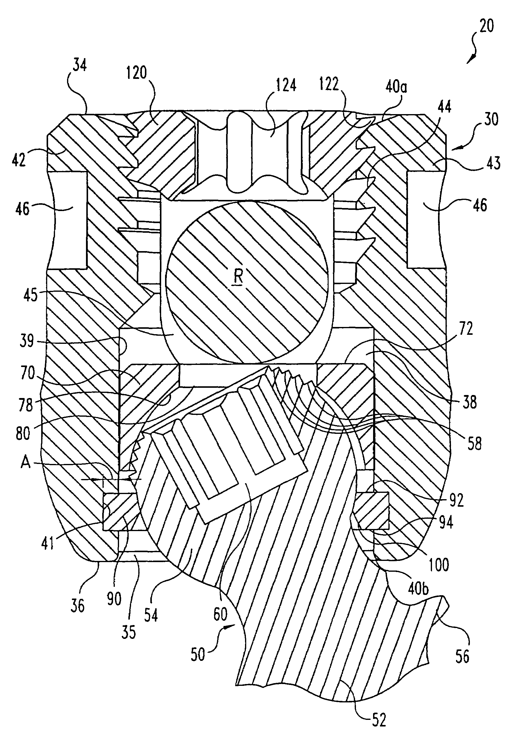
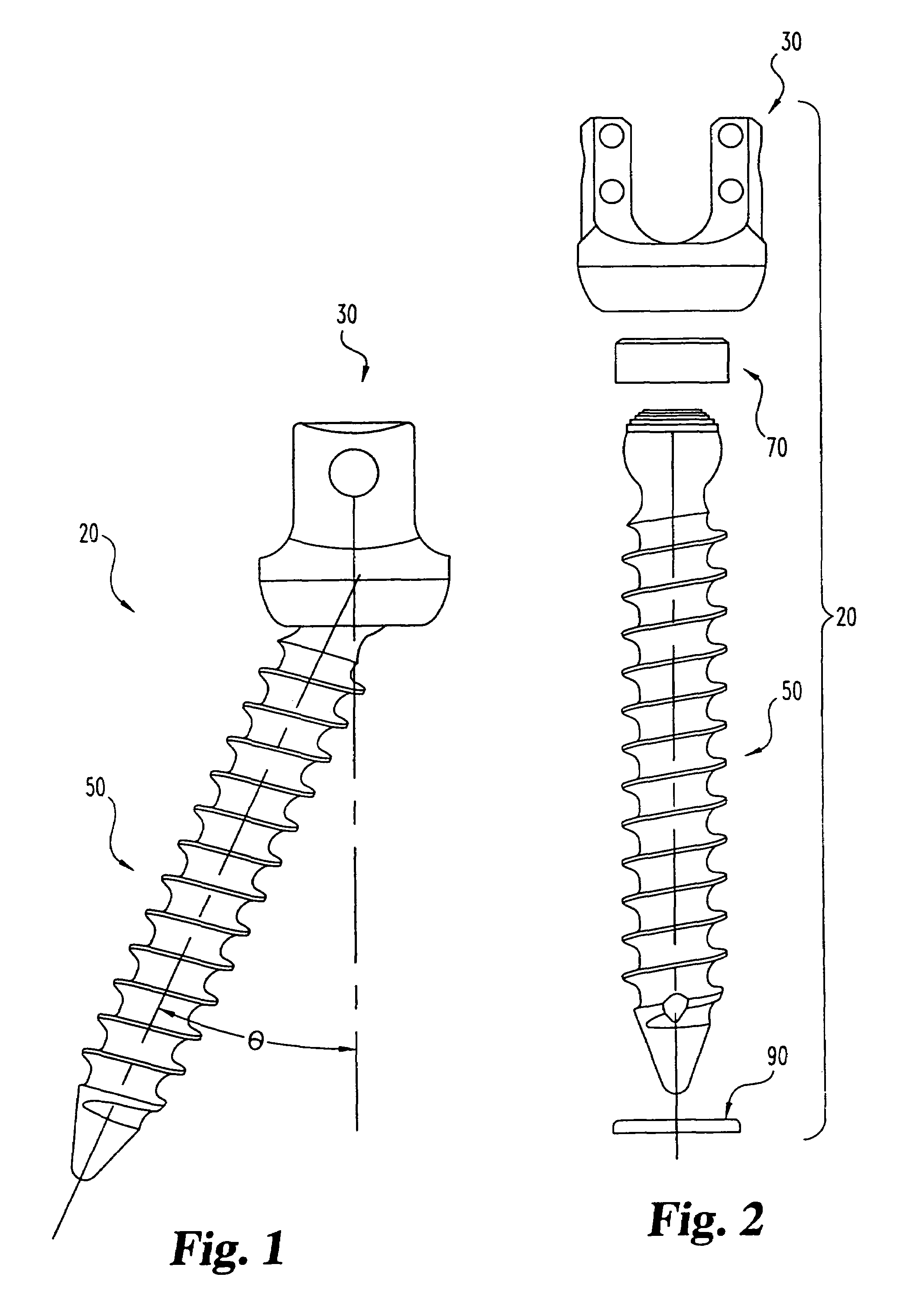
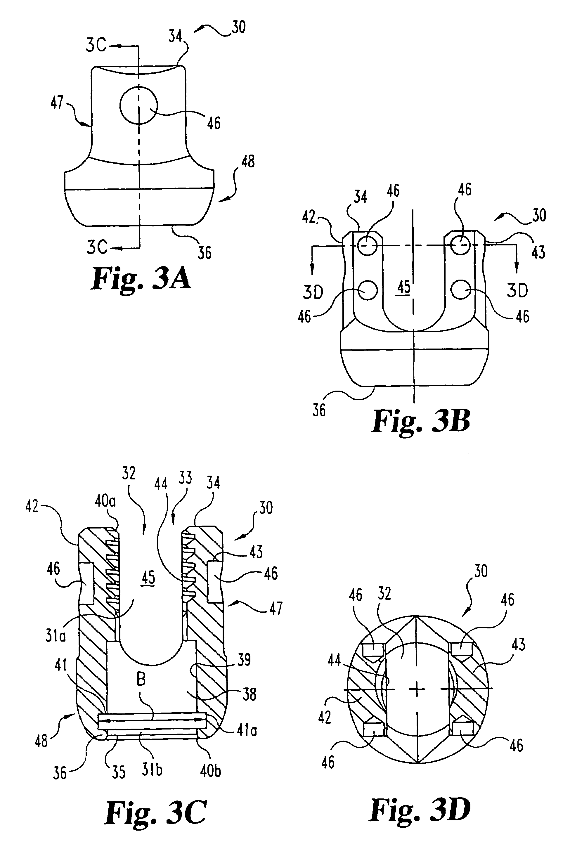
[0031]Referring generally to FIGS. 1 and 2, there is shown one embodiment of a multi-axial bone anchor assembly 20 of the present invention. In the illustrated embodiment, assembly 20 includes a receiver member 30, a bone anchor 50, a crown member 70, and a retaining member 90. The assembly 20 of the present invention is designed for use with an elongated member R (FIG. 7) such as a spinal rod, bar or other ort...


PUM


Abstract

A bottom-loading multi-axial bone anchor apparatus is disclosed. The apparatus includes a receiver member, a crown member, a bone anchor and a retaining member. The receiver member defines an upper opening and a lower opening, which may form part of the same opening, a channel, and a groove. The crown member and bone anchor are loaded into the lower opening of the receiver member, and the retaining member fits around the bone anchor and into the groove in the receiver member. The bone anchor is capable of multi-axial positioning with respect to the receiver member. An elongated member is placed in the channel of the receiver member, contacting the crown member, and a compression member is applied via the upper opening. The compression member presses down on the elongated member, which presses down on the crown member and locks the bone anchor between the crown member and the retaining member.

Description

CROSS REFERENCE TO RELATED APPLICATIONS[0001]This application claims priority to and is a continuation of U.S. patent application Ser. No. 09 / 940,902, now U.S. Pat. No. 6,660,004, filed on Aug. 28, 2001, which is a continuation of U.S. patent application Ser. No. 09 / 387,991, now U.S. Pat. No. 6,280,442, filed on Sep. 1, 1999.FIELD OF THE INVENTION[0002]The present invention relates to devices and implants used in osteosynthesis and other orthopedic surgical procedures. Specifically, the present invention contemplates a bottom loading bone anchor assembly capable of achieving multiple angular orientations with respect to an elongated member extending along bone tissue.BACKGROUND OF THE INVENTION[0003]Several techniques and systems have been developed for correcting and stabilizing damage or malformation of bones, especially the long bones and the spine. In one type of system, an elongated member such as a bendable rod is disposed longitudinally along a length of the bone(s). In spina...

Claims


Application Information

Patent Timeline
IPC IPC(8): A61B17/70A61B17/56A61B17/00A61B17/58A61B19/00
CPCA61B17/7037A61B17/7032A61B2019/307A61B2017/00858A61B2090/037
Inventor BARKER, B. THOMASYOUNG, JOHN STEWARTSQUIRES, CRAIGBRUMFIELD, DAVIDJOHNSON, CHRISBUCHANAN, DENNIS J.
Owner WARSAW ORTHOPEDIC INC
Why Eureka
Try Eureka