Multi-axial bone plate system

a multi-axial bone plate and plate system technology, applied in the field of orthopedic implant assembly system, can solve the problems of increasing the mean cost of plates and stirrups, and unable to meet the needs of patients

Inactive Publication Date: 2007-01-11
STRYKER EURO OPERATIONS HLDG LLC
View PDF50 Cites 110 Cited by
  • Summary
  • Abstract
  • Description
  • Claims
  • Application Information

AI Technical Summary

Benefits of technology

[0011] The assembly further includes a locking element having a compression member and a fixation member wherein the compression member has an aperture and at least one deformable portion. The assembly is connected to a vertebral body with the help of a bone fastener having a longitudinal axis. The bone fastener further includes a stem and a bone-engaging portion. The stem of the bone fastener may be slidably received within the aperture of the compression member. As the stem is being received by the compression m

Problems solved by technology

Although these systems are generally satisfactory, they nevertheless have certain drawbacks.
Absence of the raised patterns would lead to the risk of entirely unacceptable relative movement of the vertebrae.
The machining required to create these raised patterns significantly increases the mean cost of the plates and the stirrups.
Additionally, the raised patterns can impede fine adjustment of the system.
Moreover, if the nut is overtightened before the final tightening, lateral sliding of the plate and the stirrup during adjustment may be impeded.
Some of the drawbacks associated with other designs include that the first locking cooperation and second cooperatio

Method used


Image

  • Multi-axial bone plate system
  • Multi-axial bone plate system
  • Multi-axial bone plate system

Examples


Embodiment Construction

[0037] For the purposes of promoting and understanding the principles of the present invention, reference will now be made to the embodiment illustrated in the drawings and specification language will be used to describe the same. Nevertheless, by those skilled in the art, it will be understood that no limitation of the scope of the present invention is thereby intended, and further changes in the illustrated device may be made without deviating from the scope of the present invention.

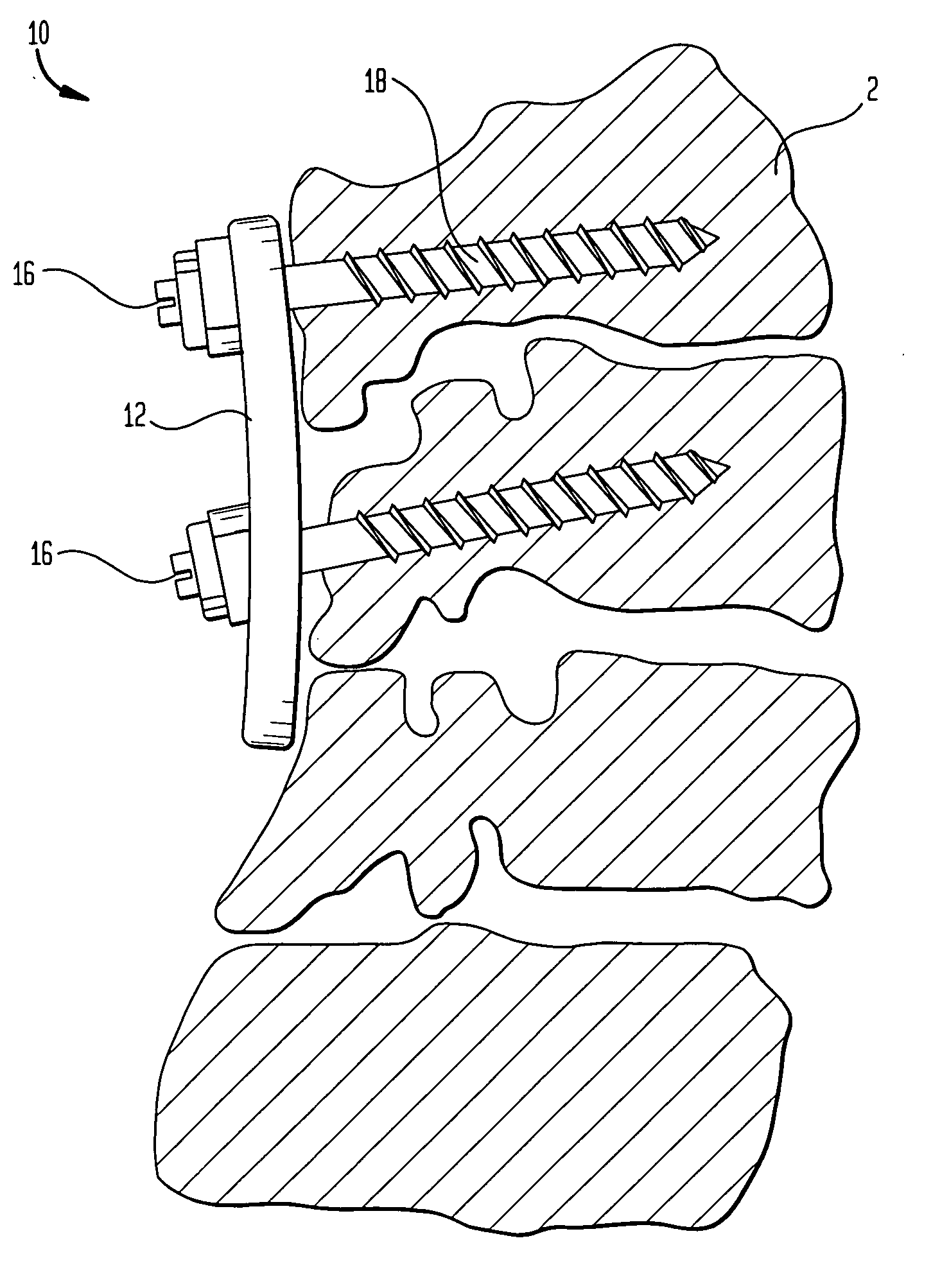
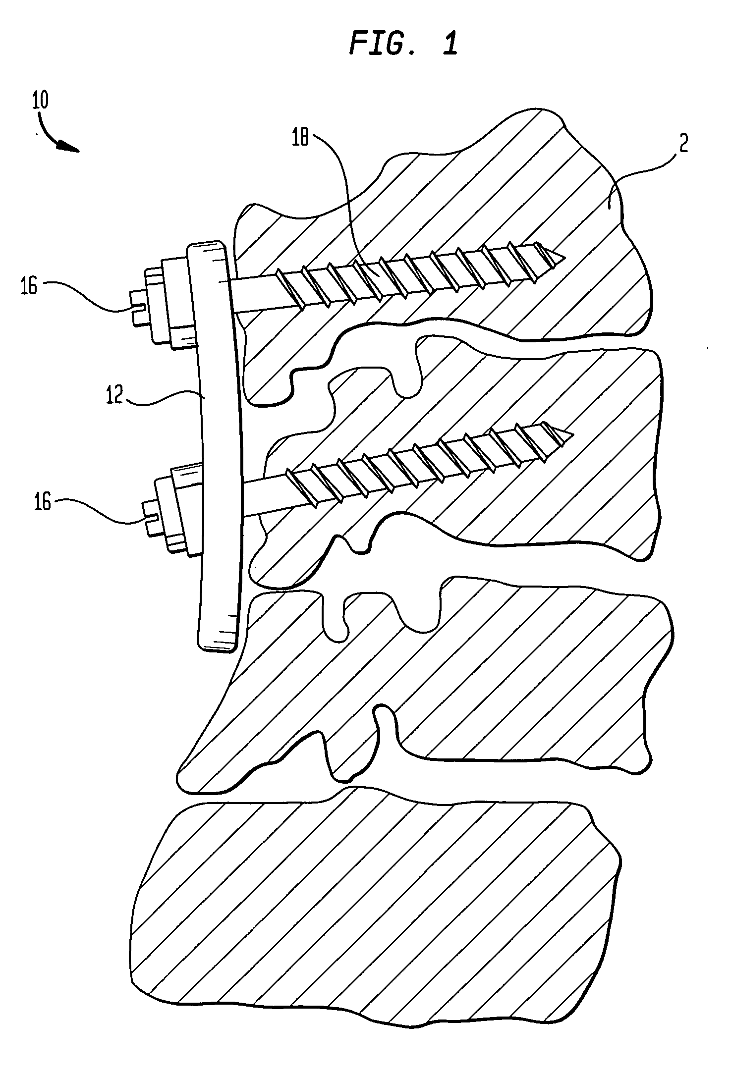
[0038] As shown in FIG. 1, the spinal implant system 10 of the present invention includes a plate 12, an expansible locking screw 16 and a bone fastener 18. As shown in the figures, bone fasteners 18 function to anchor plate 12 to vertebral bodies 2 and may be orientated at an angle with regard to the vertebral body.

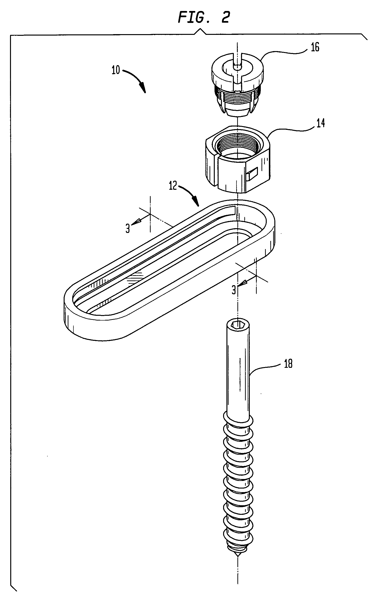
[0039]FIG. 2 details the assembly of the parts of FIG. 1 employed in the spinal implant system 10. In a preferred embodiment, the spinal implant system 10 includes an elongate member such...


PUM


Abstract

An orthopedic bone plate system having a bone plate for placement adjacent one or more vertebral bodies. The system further includes a locking element including a compression member and a fixation member wherein the compression member includes an aperture and at least one deformable portion. A bone fastener is also included in the present system which includes a bone engaging portion and a stem portion. The stem is capable of being slidably received within the aperture of the compression member while the locking member is capable of being received within an aperture of the bone plate. As the compression member is brought into proximity of a vertebral body along the longitudinal axis of the bone fastener, an increasing force is exerted against the fixation member and translated to the bone plate. The resultant force is translated back through the fixation member to the compression member which causes the deformable portion of the compression member to clamp the bone fastener relative to the bone plate.

Description

BACKGROUND OF THE INVENTION [0001] The present invention relates generally to an orthopedic implant assembly system and in particular to a multi-axial bone plate system. [0002] Orthopedic implant assembly systems having a multi-axial bone plate are known in the art and include at least two pedicular screws anchored in adjacent vertebrae to be treated and a connecting plate designed to connect the screw heads together in a rigid manner. Previous references disclose a system of this kind in which each pedicular screw has a hexagonal section part for inserting the screw into the bone and on top of which is a threaded shank. The plate has a plurality of oblong openings through which the various threaded shanks can be inserted and an open groove on its bottom face to prevent rotation of the hexagonal part of each pedicular screw. [0003] Each pedicular screw is associated with a stirrup through which the threaded shank of the screw also passes and which straddles the top of the plate. Fin...

Claims


Application Information

Patent Timeline
IPC IPC(8): A61F2/30
CPCA61B17/7059A61B17/848A61B17/8047
Inventor DE CONINCK, CEDRIC
Owner STRYKER EURO OPERATIONS HLDG LLC
Why Eureka
Try Eureka