Refrigerator

a technology of refrigerator and door handle, which is applied in the field of refrigerators, can solve the problems of large force required when a user opens the door, noise can be generated, and the appearance of the door can be easily damaged, so as to prevent the damage of an appearance of the refrigerator or noise, the effect of easy opening the door and small for

Inactive Publication Date: 2008-01-03
SAMSUNG ELECTRONICS CO LTD
View PDF7 Cites 107 Cited by
  • Summary
  • Abstract
  • Description
  • Claims
  • Application Information

AI Technical Summary

Benefits of technology

[0009]Accordingly, it is an aspect of the present invention to provide a refrigerator including a door handle, which can prevent damage of an appearance of the refrigerator or noise by an operation of the door handle, and which can permit easy opening of a door with small force being required by a user.

Problems solved by technology

Therefore, great force is required when a user opens the door.
As such, since the outer surface including paints of the compressing part 6 is likely to be abraded due to the friction, an appearance of the door can be easily damaged.
Furthermore, noise can be generated due to the friction of the compressing part 6.

Method used


Image

  • Refrigerator
  • Refrigerator
  • Refrigerator

Examples


first embodiment

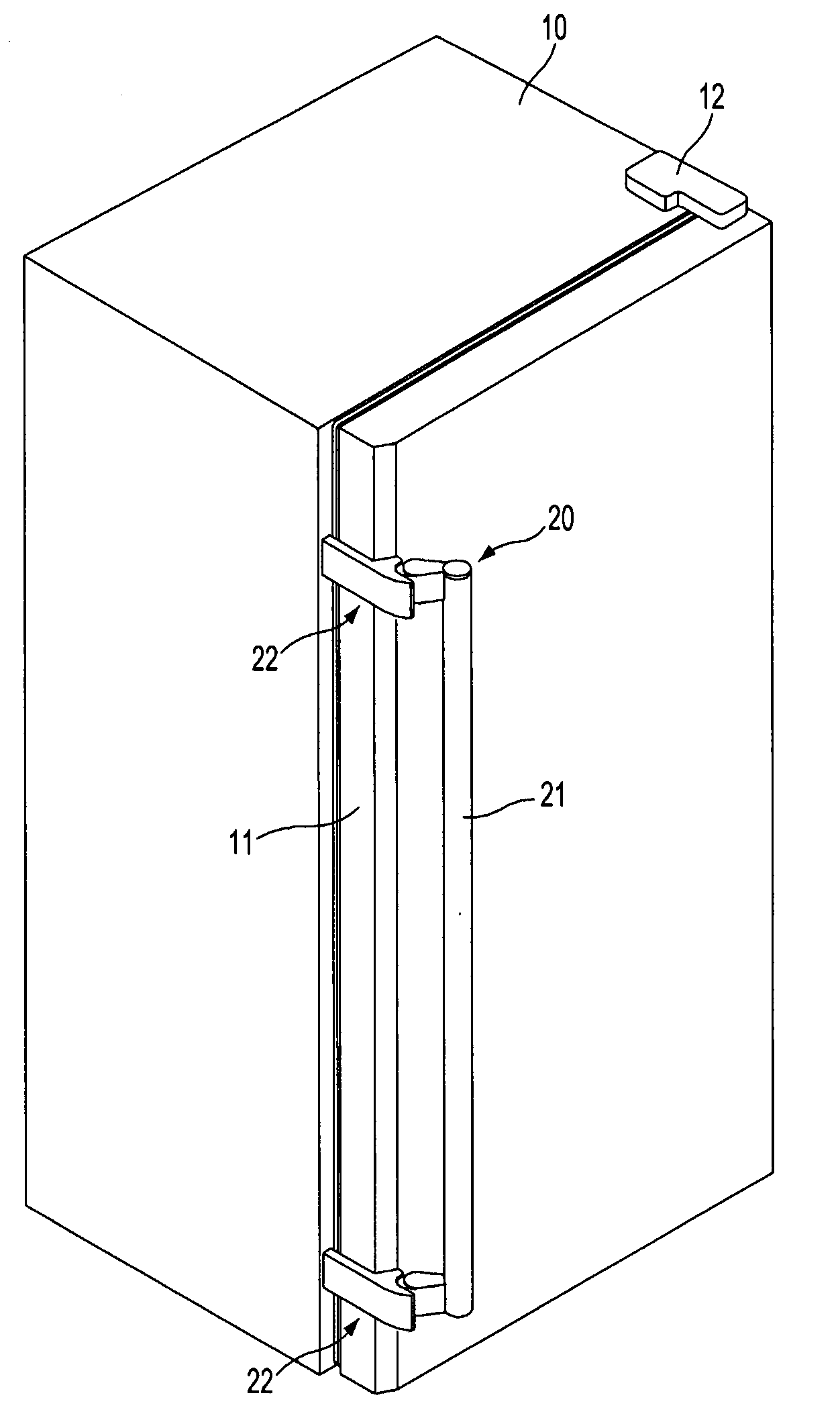
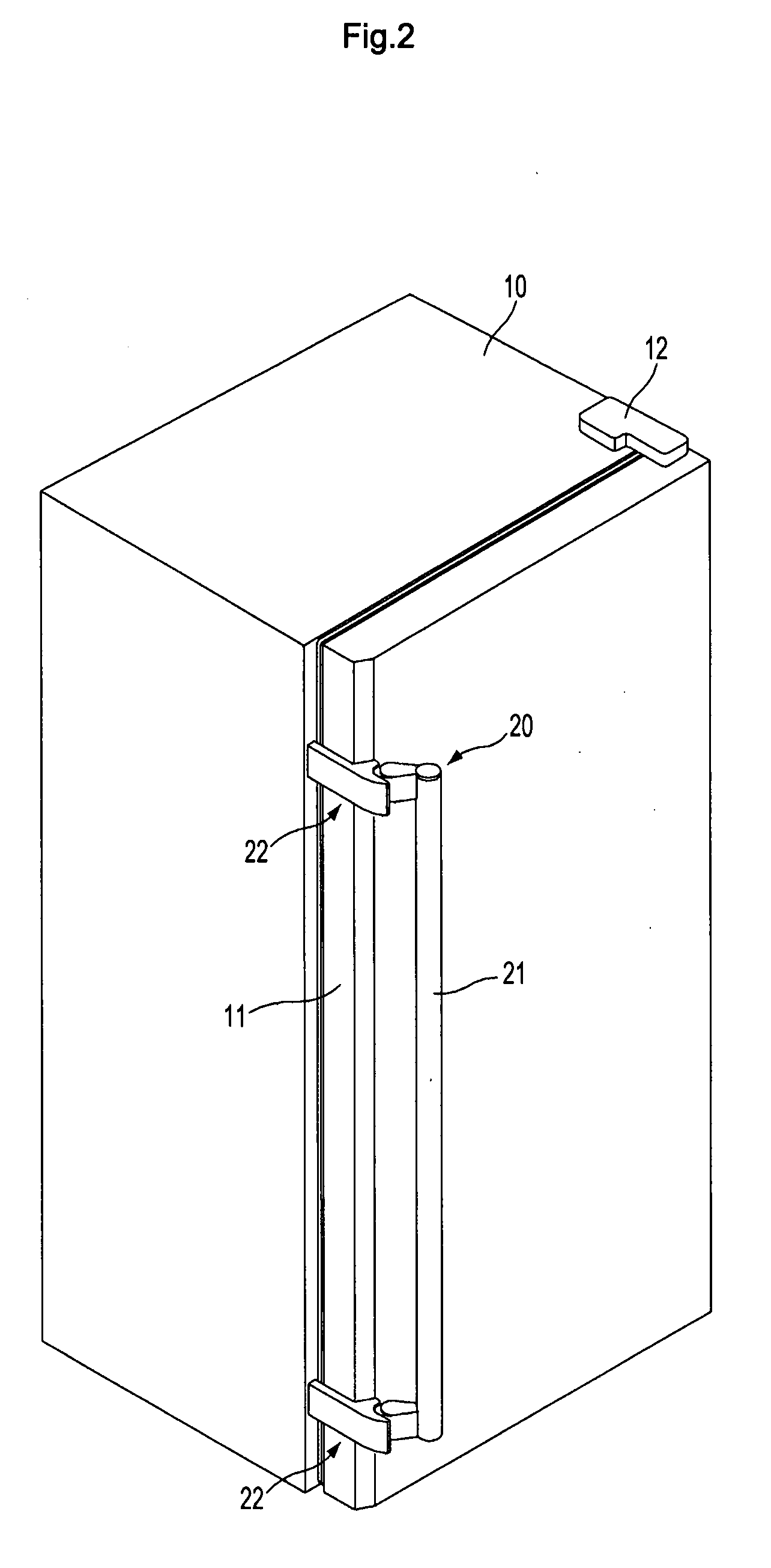
[0038]FIGS. 3-6 illustrate a door handle according to the present invention. In FIGS. 3-4, each connecting device 22 of the door handle 20 comprises a stationary member 30 fixed to the side surface of the door 11, a rotational member 40 rotatably coupled with the stationary member 30, and a compressive member 50 coupled with the stationary member 30 to linearly move by rotation of the rotational member 40. The handle 21 is fastened to the rotational member 40 by means of a fastening screw 23.

[0039]As shown in FIG. 3, the stationary member 30 comprises a planar fixed part 31 fixed to the side surface of the door 11, and an extension 32 extending from the fixed part 31 in an opening direction of the door 11 to couple with the rotational member 40. The fixed part 31 is formed with a screw fastening hole 34 to which a fastening screw 33 is fastened such that the fixed part 31 can be secured to the door 11. The fixed part 31 is formed at upper and lower sides with guide grooves 35 in a l...

third embodiment

[0059]With the door handle 200 of the third embodiment, as the rotational member 240 is rotated by pulling the handle 21, rotation of the rotational member 240 is transmitted to the second gears 244 through the first gears 243. Rotation of the second gears 244 is transmitted to the third gears 245 via the second shaft 242, and rotation of the third gears 245 is converted to a linear movement of the compressive member 250, and then transmitted to the door 11. Hence, when pulling the handle 21 to open the door 11, the compressive-member 250 moves towards and compresses the front side of the main body 10, allowing the door 11 to be opened easily.

[0060]Regarding the door handle 200 of the third embodiment, an output of the compressive member 250 can be adjusted by adjusting gear ratios of the first, second and third gears 243, 244 and 245 or by adjusting a rotational radius of the handle when manufacturing the door handle 200. Furthermore, since there is no slip on a power transmission ...


PUM


Abstract

A refrigerator includes a door handle, which can prevent damage of an appearance of the refrigerator or noise by an operation of the door handle, and which can permit easy opening of a door with a small force being required by a user. The refrigerator includes a door installed to a main body of the refrigerator, and the door handle installed on the door. The door handle includes a rotational member rotatably coupled with the door, a compressive member installed on the door, to linearly move in order to compress the main body, a gear connection part to convert a rotational movement of the rotational member to a linear movement of the compressive member, and a returning member to return the rotational member to an original position.

Description

CROSS-REFERENCE TO RELATED APPLICATIONS[0001]This application claims the benefit of Korean Patent Application No. 10-2006-0058986, filed on Jun. 28, 2006 in the Korean Intellectual Property Office, the disclosure of which is incorporated herein by reference.BACKGROUND OF THE INVENTION[0002]1. Field of the Invention[0003]The present invention relates to a refrigerator. More particularly, to a refrigerator which includes a door handle to permit easy opening of a door by a user.[0004]2. Description of the Related Art[0005]A conventional refrigerator includes a large, heavy door which has a difference in pressure between an interior and an exterior of a storage compartment due to a decrease in temperature inside the storage compartment. Therefore, great force is required when a user opens the door. Accordingly, the conventional refrigerator includes a device, for example, a handle apparatus to permit opening of the door by a user.[0006]For example, a conventional refrigerator as disclos...

Claims


Application Information

Patent Timeline
Patent Type & Authority Applications(United States)
IPC IPC(8): E05D5/00
CPCE05B17/0033Y10T16/554F25D23/028F25D23/02F25D23/00
Inventor HONG, DAE JINJEONG, GI JOONGSONG, YO HYUNJUNG, SANG GYU
Owner SAMSUNG ELECTRONICS CO LTD
Why Eureka
Try Eureka