
gas stove

A technology for gas stoves and stoves, which is applied in the directions of burners, combustion methods, heating fuels, etc., can solve the problems of supplying primary air, difficult necks, and easy accumulation of heat in stove burners.

Inactive Publication Date: 2016-01-20
RINNAI CORP
View PDF3 Cites 0 Cited by
  • Summary
  • Abstract
  • Description
  • Claims
  • Application Information

AI Technical Summary

Problems solved by technology

Therefore, the flow state of the primary air flowing in from the primary air inlet toward the neck tends to bend or meander, making it difficult to smoothly supply the primary air to the neck.
[0007] Moreover, since the interior of the stove body is surrounded by the peripheral wall and the bottom wall of the stove body, the stove burner easily accumulates heat.
Therefore, the air flow inside the stove body tends to become uneven due to the heat accumulated inside the stove body, making it difficult to supply a sufficient amount of primary air to the neck.

Method used


Image

  • gas stove
  • gas stove
  • gas stove

Examples


Embodiment Construction

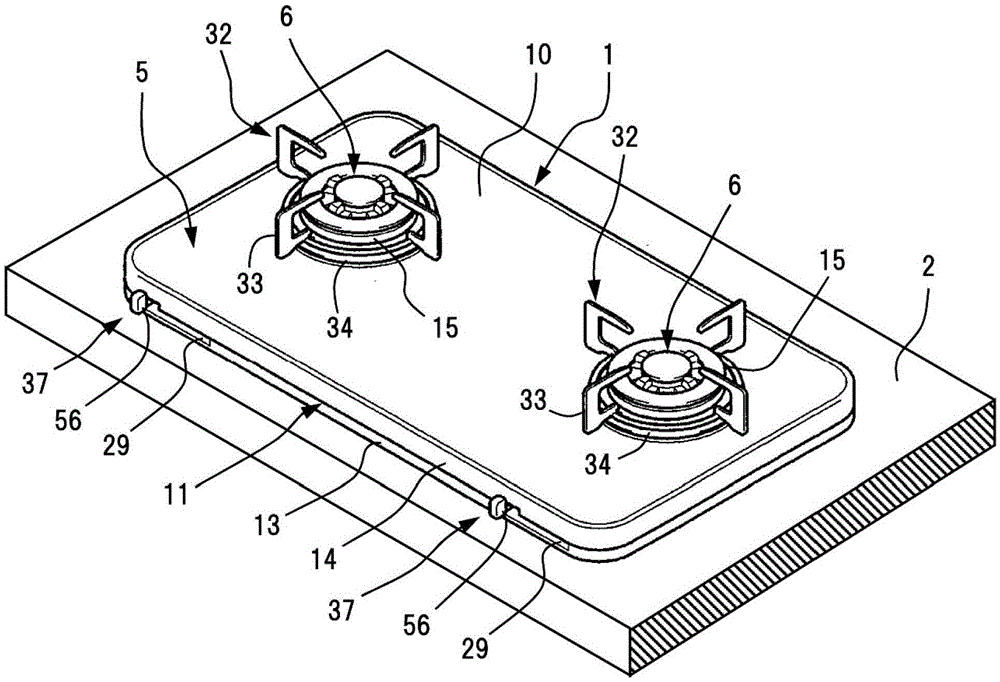
[0023] An embodiment of the present invention will be described with reference to the drawings. Such as figure 1 As shown, the gas stove 1 of the present embodiment is a built-in stove, so as to fall into the opening 3 for the stove (refer to figure 2 ) way to set. Wherein, the opening 3 for a stove is formed on a countertop 2 of a kitchen unit.

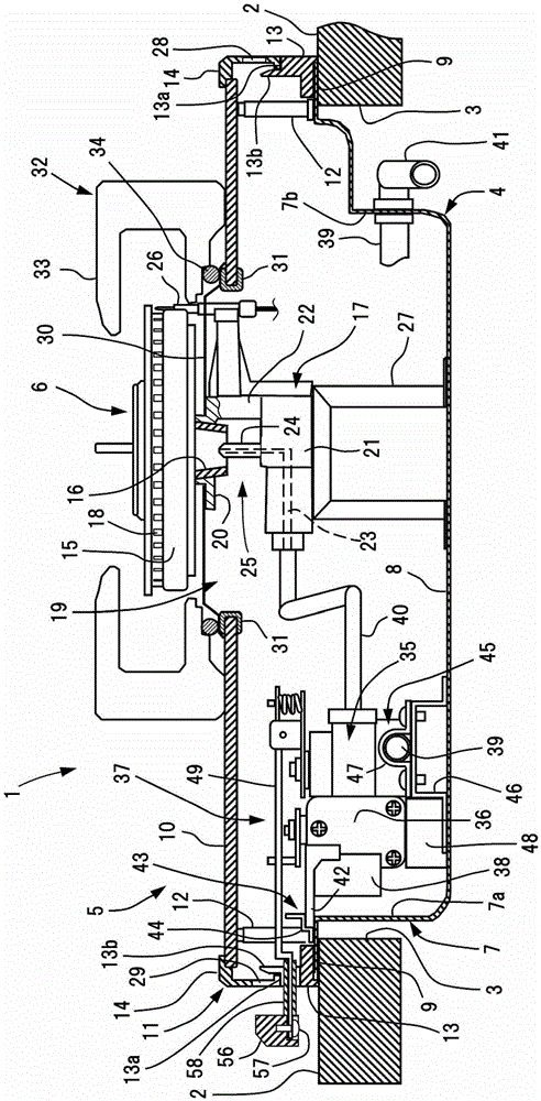
[0024] Such as figure 2 As shown, the gas stove 1 includes a stove main body 4 , a panel portion 5 , and a stove burner 6 . Such as image 3 As shown, the main body 4 of the furnace is composed of a substantially square cylindrical peripheral wall 7 and a bottom wall 8 closing the bottom of the peripheral wall 7 . A flange portion 9 protruding horizontally outward is formed on the upper end of the peripheral wall 7 of the furnace main body 4 . The flange portion 9 is hung and fixed on the upper surface of the periphery of the opening 3 for a stove. Thereby, the stove main body 4 is in the installation state suspended inside ...


PUM


Abstract

The invention provides a gas stove. The gas stove comprises a stove main body (4) disposed in the bench surface; a panel part (5) and a stove burner (6), which are disposed on the bench surface (2). The stove burner is provided with a burner head part (15), a neck part (16), a holding part (17), and a nozzle (24) capable of spraying fuel gas from a lower part of the neck part. A peripheral part of the nozzle in the horizontal direction can be used as a primary air suction part (25) used to supply the primary air for the neck part. The panel part is provided with a panel (10) and a frame (11). At least two opposite side walls of the frame are respectively provided with the primary air inlet ports (28, 29) having openings along the horizontal direction. The primary air suction part (25) is disposed in the panel part (5). Even the gas stove is disposed on the bench surface, the primary air can be successfully supplied for the stove burner, and enough primary air can be supplied for the stove burner, therefore the well combustion of the stove burner can be realized.

Description

technical field [0001] The invention relates to a gas stove. Background technique [0002] A so-called built-in gas stove installed on a countertop of a kitchen unit is composed of a stove main body and a panel portion. The main body of the stove is arranged at a lower position than the upper surface of the table, and the panel part covers the upper surface of the main body of the stove and is exposed above the upper surface of the table. [0003] The main body portion of the stove burner is housed inside the stove body. Inside the stove main body of the stove burner, primary air for combustion is sucked in at the same time as fuel air is sucked in from a neck portion facing a nozzle that ejects fuel gas in the horizontal direction. [0004] In such a gas stove, primary air is taken in from a primary air inlet provided on a peripheral wall, a bottom wall, or the like of the stove main body. However, since the main body of the stove is located inside the countertop, the pr...

Claims


Application Information

Patent Timeline
Patent Type & Authority Patents(China)
IPC IPC(8): F24C3/08F23D14/46
Inventor 水谷嘉宏
Owner RINNAI CORP
Learn More