Bottom plate assembly turnover mechanism

A flipping mechanism and pairing technology, applied in the direction of climate sustainability, final product manufacturing, manufacturing tools, etc., can solve the problems of affecting precision, high labor intensity, and low efficiency, so as to improve efficiency, reduce labor intensity, and ensure consistent effect

Pending Publication Date: 2022-08-02
南京合信自动化有限公司
View PDF0 Cites 0 Cited by
  • Summary
  • Abstract
  • Description
  • Claims
  • Application Information

AI Technical Summary

Problems solved by technology

[0004] Based on the clamping method in the prior art, it is necessary to clamp from the workpiece, and the positioning model cannot accurately locate the blank shape of the workpiece, which is easy to affect the accuracy, and the manual upper platen is fixed, which has the technical problems of low efficiency and high labor intensity. The present invention Proposes a base plate pair turning mechanism

Method used


Image

  • Bottom plate assembly turnover mechanism
  • Bottom plate assembly turnover mechanism
  • Bottom plate assembly turnover mechanism

Examples


Embodiment Construction

[0024] The technical solutions in the embodiments of the present invention will be clearly and completely described below with reference to the accompanying drawings in the embodiments of the present invention. Obviously, the described embodiments are only a part of the embodiments of the present invention, but not all of the embodiments.

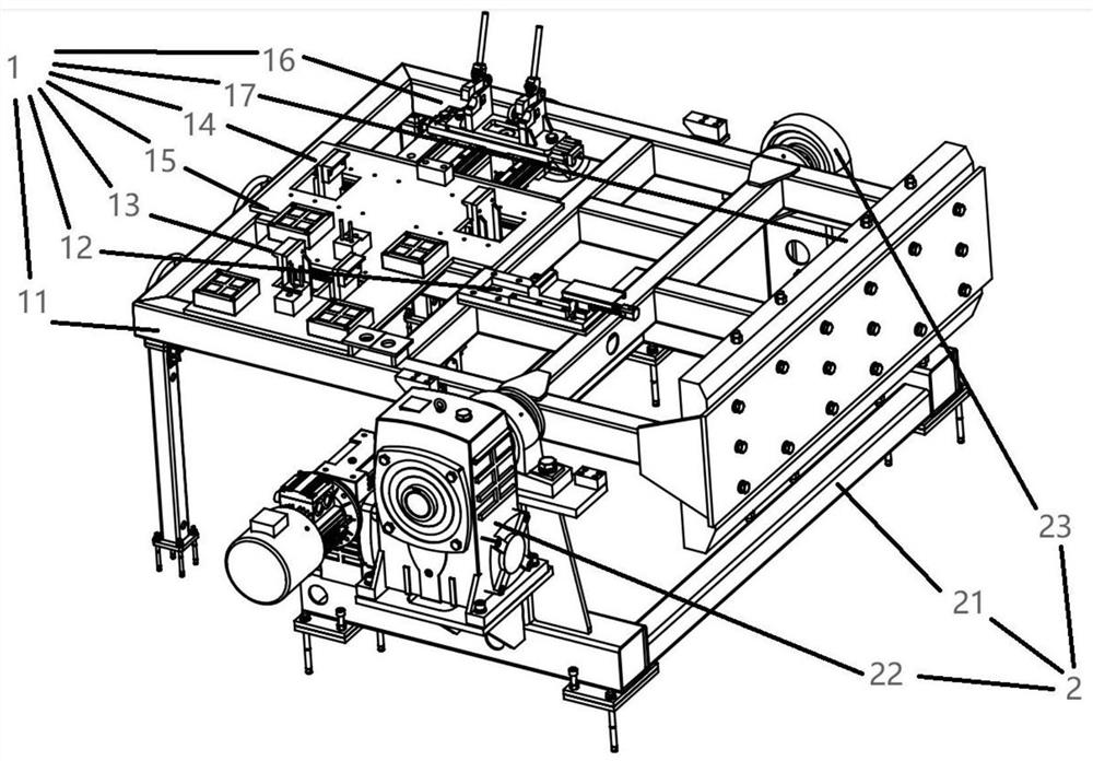
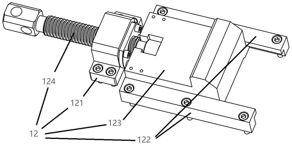
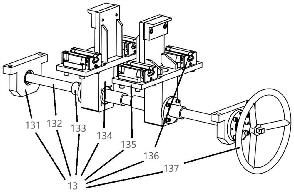
[0025] refer to figure 1 , a bottom plate group pair flipping mechanism, including a clamp assembly 1 and a flipping positioner 2, the clamp assembly 1 includes a flipping frame 11, a side positioning mechanism 12, a first centering and positioning mechanism 13, and a second centering and positioning mechanism 14 , electric permanent magnet 15, movable ear plate positioning mechanism 16 and counterweight 17, side positioning mechanism 12, first centering positioning mechanism 13, second centering positioning mechanism 14, electro permanent magnet 15, movable ear plate positioning mechanism 16 and the counterweight 17 are both located on the...


PUM


Abstract

The invention belongs to the technical field of workpiece turnover, particularly relates to a bottom plate assembly turnover mechanism, and provides the following scheme aiming at the problems of low precision and low production efficiency: the bottom plate assembly turnover mechanism comprises a clamp assembly and a turnover positioner, the clamp assembly comprises an overturning frame, a side positioning mechanism, a first centering positioning mechanism, a second centering positioning mechanism, an electric permanent magnet, a movable lug plate positioning mechanism and a balance weight. The side positioning mechanism, the first centering positioning mechanism, the second centering positioning mechanism, the electric permanent magnet, the movable lug plate positioning mechanism and the balance weight are all located on the overturning frame. The turnover positioner comprises a base, a driving motor and a rotary bearing seat, and the base is located below the turnover frame. After a workpiece is fed, a first hand wheel is rotated to drive a first lead screw to rotate, the first lead screw is matched with a first lead screw nut and a first nut seat to drive two first fixing block sliding plates to do relative motion, and therefore the two first fixing block sliding plates can be controlled to clamp the workpiece.

Description

technical field [0001] The invention relates to the technical field of workpiece inversion, in particular to a bottom plate group pair inversion mechanism. Background technique [0002] In the prior art, when positioning the workpiece, shape positioning, pressure plate fixing, and fixed pin positioning lugs are used for grouping and processing. After the processing is completed, in order to ensure the requirements of subsequent processes, manual lifting is required to turn it over. [0003] This clamping method needs to be clamped from the workpiece, and the positioning template cannot accurately locate the blank shape of the workpiece, which easily affects the accuracy, and the manual upper platen is fixed, which has the problems of low efficiency and high labor intensity. It is easy to get stuck, and it is easy to cause the problem of large deformation, which affects the accuracy of the parts. After the assembly is completed, the material needs to be turned over, which is ...

Claims


Application Information

Patent Timeline
Patent Type & Authority Applications(China)
IPC IPC(8): B25B11/00
CPCB25B11/00Y02P70/50Y02E60/10
Inventor 张浩戴晓春梅庆峰汪华陈文茂胡新波李航
Owner 南京合信自动化有限公司
Why Eureka
Try Eureka