Piezoelectric actuator with a sheath, for disposition in a piezoelectric injector

a technology of piezoelectric actuators and sheathes, which is applied in the direction of mechanical equipment, generators/motors, machines/engines, etc., can solve the problems of rigid sleeve and diaphragm arrangement as a sheath that cannot withstand the high system, and the known concept cannot be readily adopted, etc., to achieve good sealing action, simple and durable, and economic

a technology of piezoelectric actuators and sheathes, which is applied in the direction of mechanical equipment, generators/motors, machines/engines, etc., can solve the problems of rigid sleeve and diaphragm arrangement as a sheath that cannot withstand the high system, and the known concept cannot be readily adopted, etc., to achieve good sealing action, simple and durable, and economic

US7728489B2Inactive Publication Date: 2010-06-01ROBERT BOSCH GMBH

Image

  • Piezoelectric actuator with a sheath, for disposition in a piezoelectric injector
  • Piezoelectric actuator with a sheath, for disposition in a piezoelectric injector
  • Piezoelectric actuator with a sheath, for disposition in a piezoelectric injector

Examples


Embodiment Construction

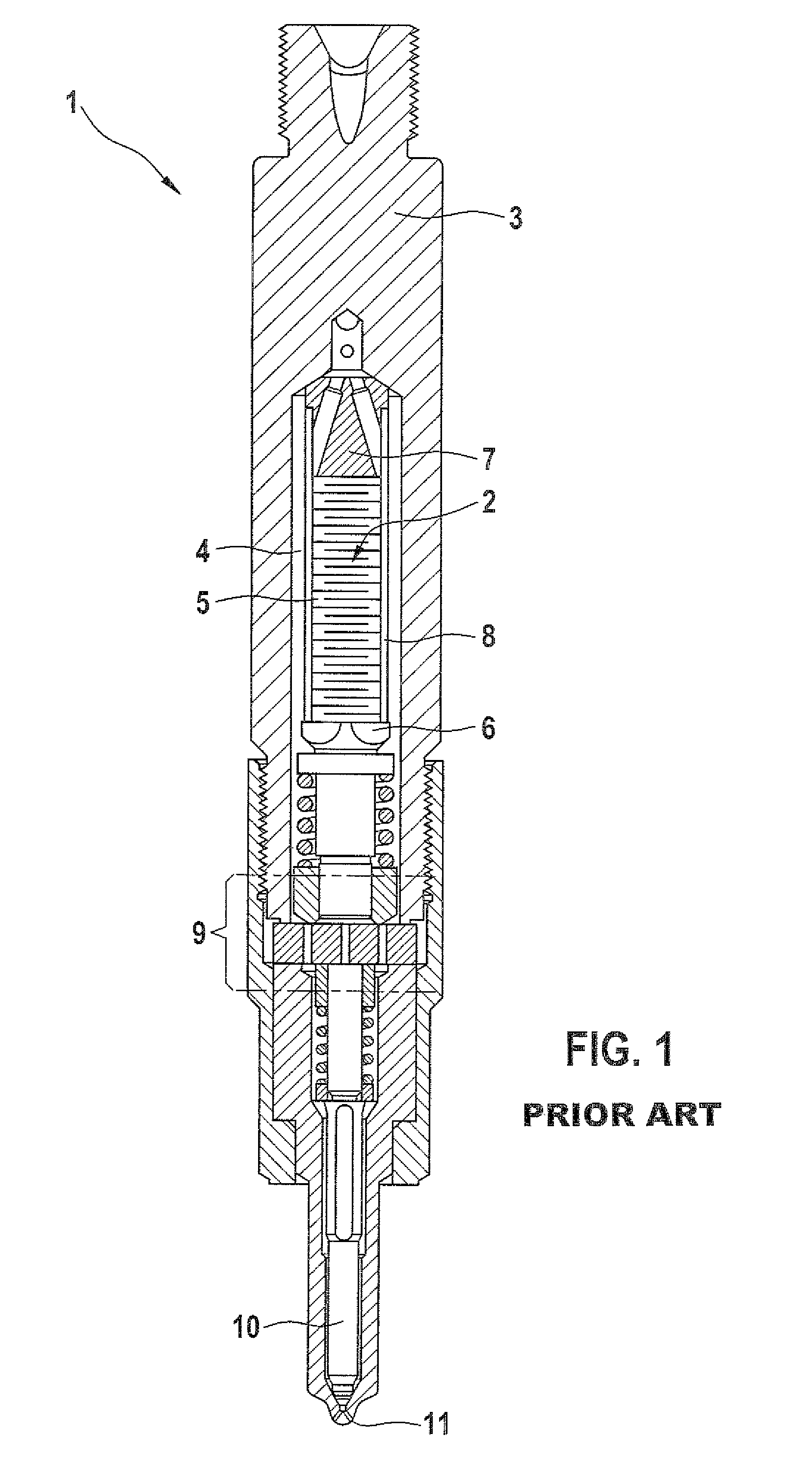
[0028]In FIG. 1, a basic construction of a piezoelectric injector 1 with a piezoelectric actuator 2 of the prior art is shown, which can be used for instance for needle stroke control in an injection system for fuel in an internal combustion engine. In the upper part, there is a holder body 3, which can be adapted in its geometric dimensions essentially to the particular intended application and the specific location where it will be used. By means of the holder body 3, with a specifically adapted plug embodiment, the electrical voltage is carried for triggering piezoelectric elements 5, which are stacked one above the other in an inner chamber 4 of the holder body 3 and which together with an actuator head 6 and an actuator foot 7 form the piezoelectric actuator 2. An insulating sleeve 8 shown here only schematically is placed as a sheath around the piezoelectric actuator 2.

[0029]Upon an actuation, as mentioned in the background section in terms of a piezoelectric injector, the pie...


PUM


Abstract

A piezoelectric actuator with piezoelectric elements, fastened between an actuator head and an actuator foot, and with a plastic sleeve surrounding at least the piezoelectric elements is proposed, which is set in a clamping ring on the actuator head and / or the actuator foot of the piezoelectric actuator. The respective clamping ring may be a metal part or a plastic part, which is equipped with clamping lugs suitable for setting the plastic sleeve and is thrust, pressed, or shrunk onto the respective actuator head and / or actuator foot of the steel piezoelectric actuator.

Description

REFERENCE TO FOREIGN PATENT APPLICATION[0001]This application is based on German Patent Application No. 10 2006 045 663.7 filed 27 Sep. 2006, upon which priority is claimed.BACKGROUND OF THE INVENTION[0002]1. Field of the Invention[0003]The invention relates to a piezoelectric actuator sheathed with a sleeve and bathed for instance by liquid media, which can be inserted into a piezoelectric injector for chronologically and quantitatively precise metering of fuel for an internal combustion engine. A piezoelectric injector of this kind substantially comprises a holder body and the piezoelectric actuator disposed in the holder body, the piezoelectric actuator having piezoelectric elements stacked one above the other and disposed in an actuator head and an actuator foot.[0004]2. Description of the Prior Art[0005]It is known per se that for constructing a piezoelectric actuator of the type described above, the piezoelectric elements can be inserted in such a way that by utilizing the so-...

Claims


Application Information

Patent Timeline
01 Jun 2010
Publication
US7728489B2
IPC
H01L41/08; H10N30/00; H10N30/80; H10N30/88
CPC
F02M51/0603; H01L41/053; F02M2200/703; F02M63/0057; H10N30/88
Inventors
HEINZ, RUDOLF; KIENZLER, DIETER