Wear assembly

a technology for wearing parts and components, applied in the direction of rod connections, fastening means, constructions, etc., can solve the problems of wear members that are commonly subject to harsh conditions and heavy loading, wear members that need to be replaced, etc., to achieve the effect of less risk to the user and easy assembly on the lip or other equipmen

Active Publication Date: 2010-06-08
ESCO GRP LLC
View PDF25 Cites 32 Cited by
  • Summary
  • Abstract
  • Description
  • Claims
  • Application Information

AI Technical Summary

Benefits of technology

[0011]In one aspect of the invention, an improved spool is used with a wedge to hold the wear member in place. The spool is formed with at least one laterally extending arm at its upper end in lieu of an axial arm such as used in a conventional C-shaped spool. In this way, the spool can be easily supported in the assembly as the wedge is installed. The spool does not fall through the opening and no special care is needed to prevent it from falling. As a result, installation of the wear assembly is easier and less hazardous. In addition, the lateral support reduces the risk that the spool will suffer spreading.
[0013]Similarly, in another aspect of the invention, the wear member is formed with an opening having at least one spool support for receiving and holding a spool with a lateral arm. Preferably, the wear member is formed with a side recess as the spool support to each side of the lock-receiving opening. As noted above, this new construction enables the wear member to be assembled on the lip or other equipment more easily and with less risk to the user.

Problems solved by technology

Such wear members are commonly subjected to harsh conditions and heavy loading.
Accordingly, the wear members wear out over a period of time and need to be replaced.
As a result, the spool at times can slip through the lip and fall to the ground requiring the worker to retrieve it from under the bucket.
This can be a difficult process particularly if installation is being done at night.
In addition, crawling under the bucket can place the worker in a potentially hazardous position.
A large hammer is required to install the wedge into the assembly, which places the worker in a potentially hazardous position for injury from pieces that may fly off during hammering.
The large forces applied to the spool arms can result in spreading of the arms.
Such spreading reduces the grip of the lock on the wear member and can at times lead to failure of the lock.

Method used


Image

  • Wear assembly
  • Wear assembly
  • Wear assembly

Examples


Embodiment Construction

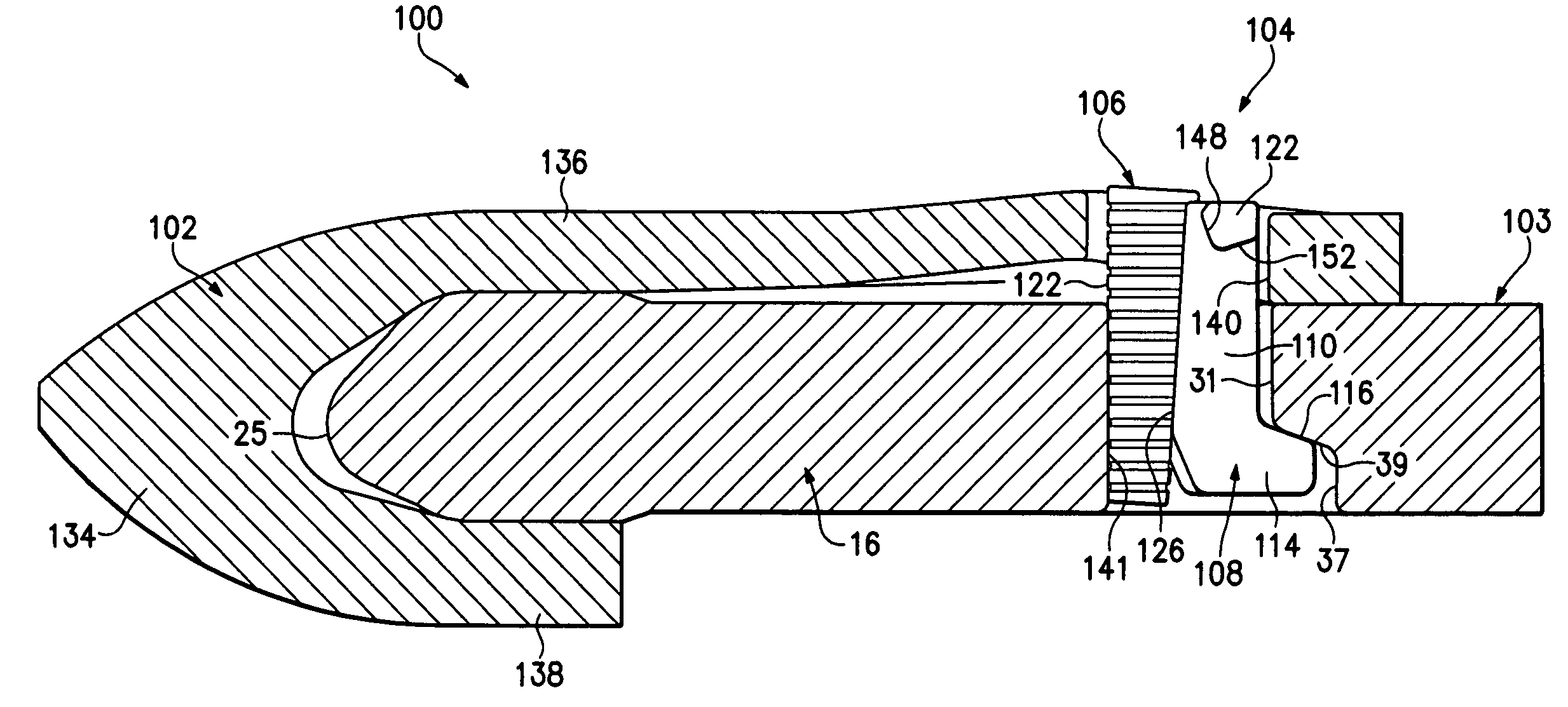
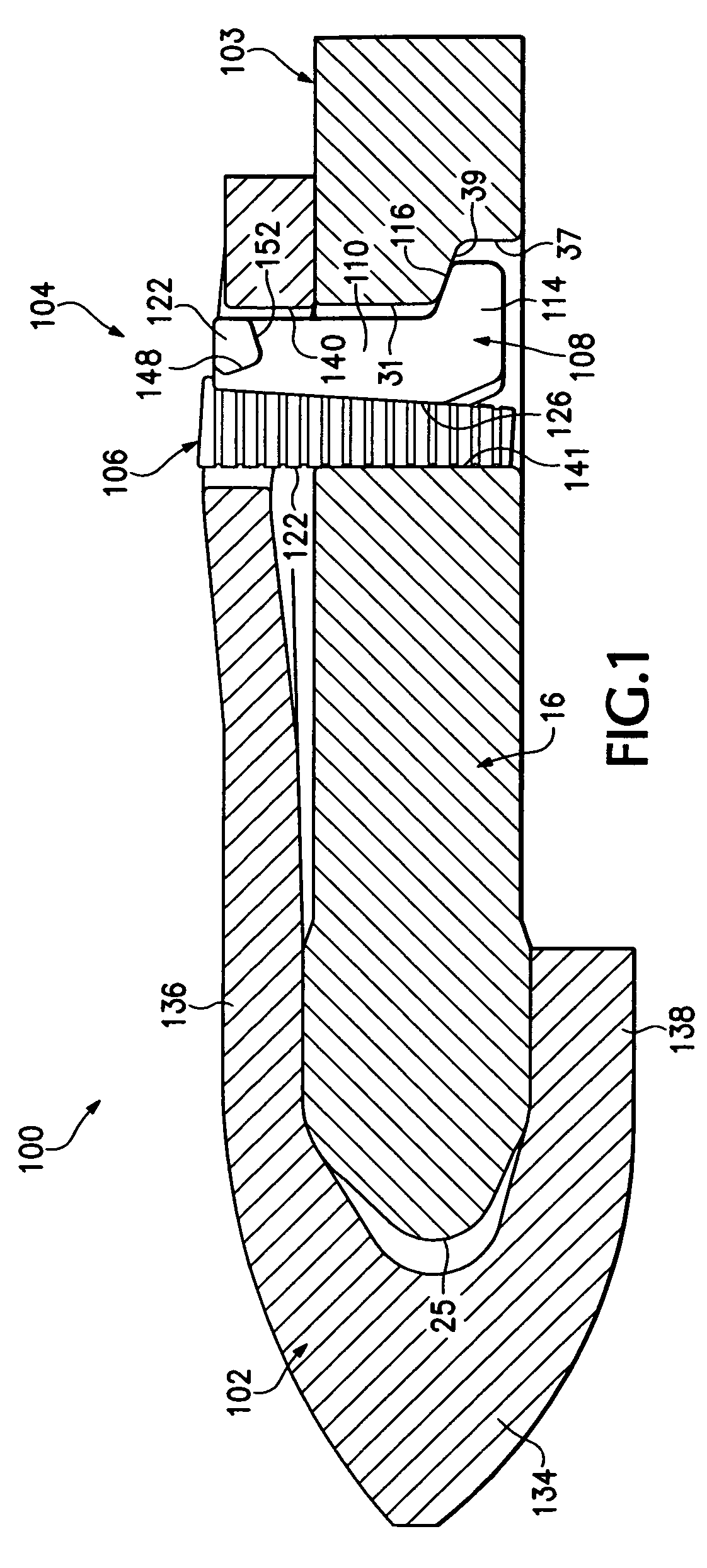
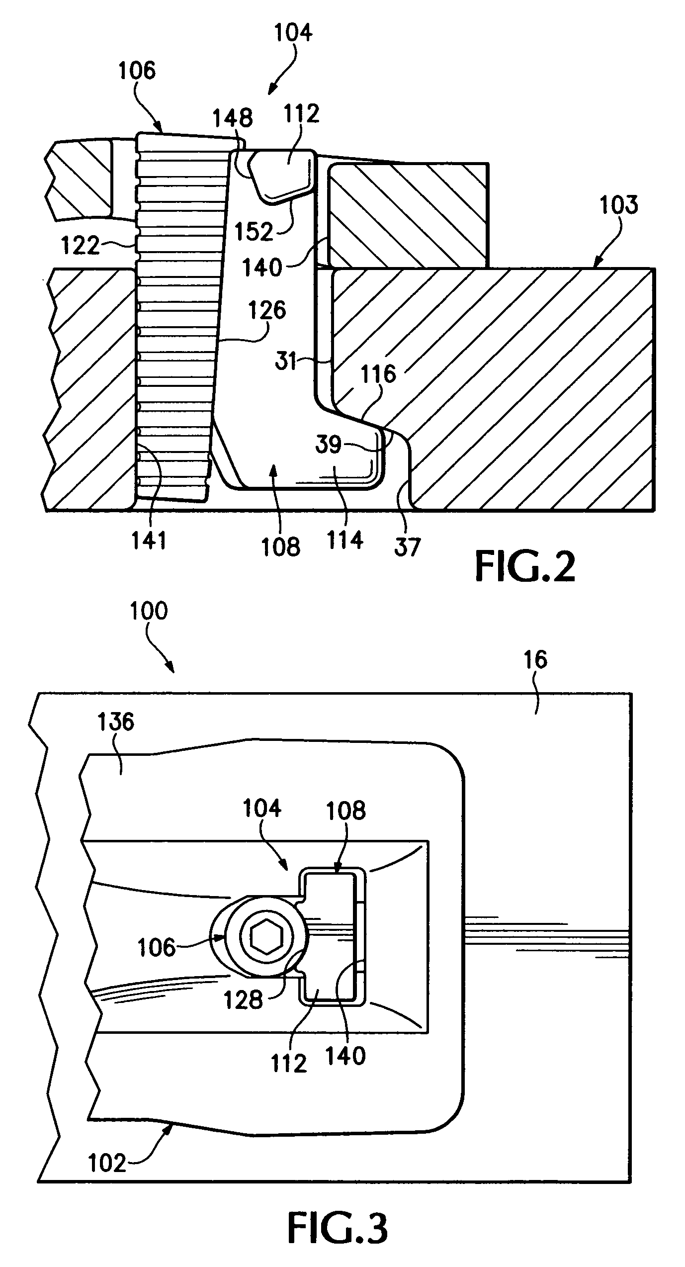
[0033]The present invention pertains to a wear assembly 100 in which a wear member 102 is releasably attached to excavating equipment 103 (FIGS. 1-4). In this application, wear member 102 is described in terms of a shroud that is attached to a lip of an excavating bucket. However, wear member 102 could be in the form of other kinds of products (e.g., adapters, wings, etc.) attached to other equipment. Moreover, relative terms such as forward, rearward, up or down are used for convenience of explanation with reference to the drawings; other orientations are possible.

[0034]In one embodiment (FIGS. 1-4), shroud 102 fits on a conventional lip 16. Although the lip in FIG. 1 is slightly different than in FIG. 19, for convenience, the same numbers are used to identify the lip and its features. The particular lip construction is not critical for the invention, and an assembly in accordance with the present invention can be used with a wide range of lips.

[0035]Lock 104 includes a wedge 106 a...


PUM


Abstract

In a wear assembly for securing wear members to excavating equipment, a spool is used with a wedge to hold the wear member in place. The spool is formed with at least one laterally extending arm at its upper end in lieu of an axial arm such as used in a conventional C-shaped spool. In this way, the spool can be easily supported in the assembly as the wedge is installed. The spool does not fall through the opening and no special care is needed to prevent it from falling. The spool also holds itself in place when the wedge is driven into the passage. As a result, installation of the wear assembly is easier and less hazardous. In addition, the lateral support reduces the risk that the spool will suffer spreading.

Description

FIELD OF THE INVENTION[0001]The present invention pertains to a wear assembly for securing a wear member to an excavating bucket or the like.BACKGROUND OF THE INVENTION[0002]Wear members in the form of adapters, shrouds, and the like are ordinarily secured to the front edge of an excavating bucket. Such wear members are commonly subjected to harsh conditions and heavy loading. Accordingly, the wear members wear out over a period of time and need to be replaced. The wear members are made to withstand the rigors of a digging operation and still be capable of replacement when worn. Whisler-style locking arrangements have long been in use for mechanically attaching wear members to the lip of a bucket. Such locks generally consist of a wedge and a C-shaped clamp or spool. While the wedge is typically hammered into the assembly, U.S. Pat. Nos. 4,433,496 and 5,964,547 disclose arrangements wherein the wedge is drawn into place under pressure from a screw. U.S. Patent Application Publicatio...

Claims


Application Information

Patent Timeline
Patent Type & Authority Patents(United States)
IPC IPC(8): E02F9/28
CPCE02F9/2833E02F9/2883Y10T403/7069E02F9/28
Inventor MCCLANAHAN, ROBERTBRISCOE, TERRY L.
Owner ESCO GRP LLC
Why Eureka
Try Eureka