Electrical connector with improved buckling tab

Inactive Publication Date: 2010-06-08
CHENG UEI PRECISION IND CO LTD
View PDF5 Cites 8 Cited by
  • Summary
  • Abstract
  • Description
  • Claims
  • Application Information

AI Technical Summary

Benefits of technology

[0006]As described above, the electrical connector has the upper resistive portion and the propping portion, which are both against the inserted mating plug. Furthermore, the upper resistive portion makes the propping portion uplift when the upper resistive portion is pressed downwardly, and the propping portion is also enable to raise the upper resistive portion when the propping portion is pressed downwardly, accordingly, which not only enhances the insertion and withdrawal force between the electrical connector and the mating plug, but also prolongs usage life of the electrical connector.

Problems solved by technology

Furthermore, the upper resistive portion makes the propping portion uplift when the upper resistive portion is pressed downwardly, and the propping portion is also enable to raise the upper resistive portion when the propping portion is pressed downwardly, accordingly, which not only enhances the insertion and withdrawal force between the electrical connector and the mating plug, but also prolongs usage life of the electrical connector.

Method used


Image

  • Electrical connector with improved buckling tab
  • Electrical connector with improved buckling tab
  • Electrical connector with improved buckling tab

Examples


Embodiment Construction

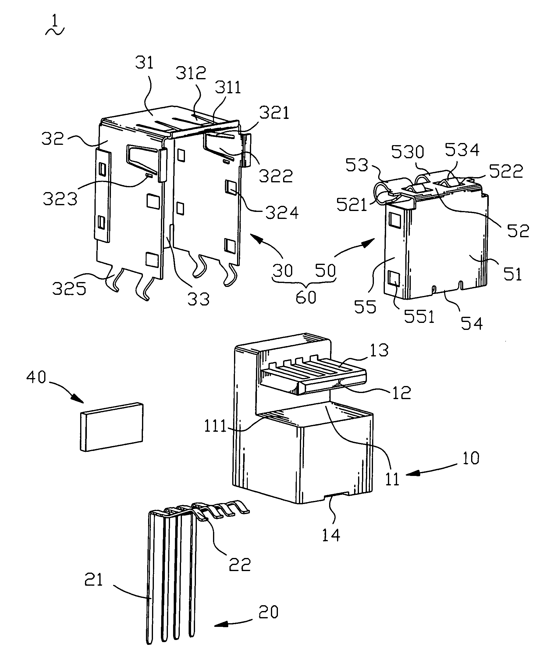
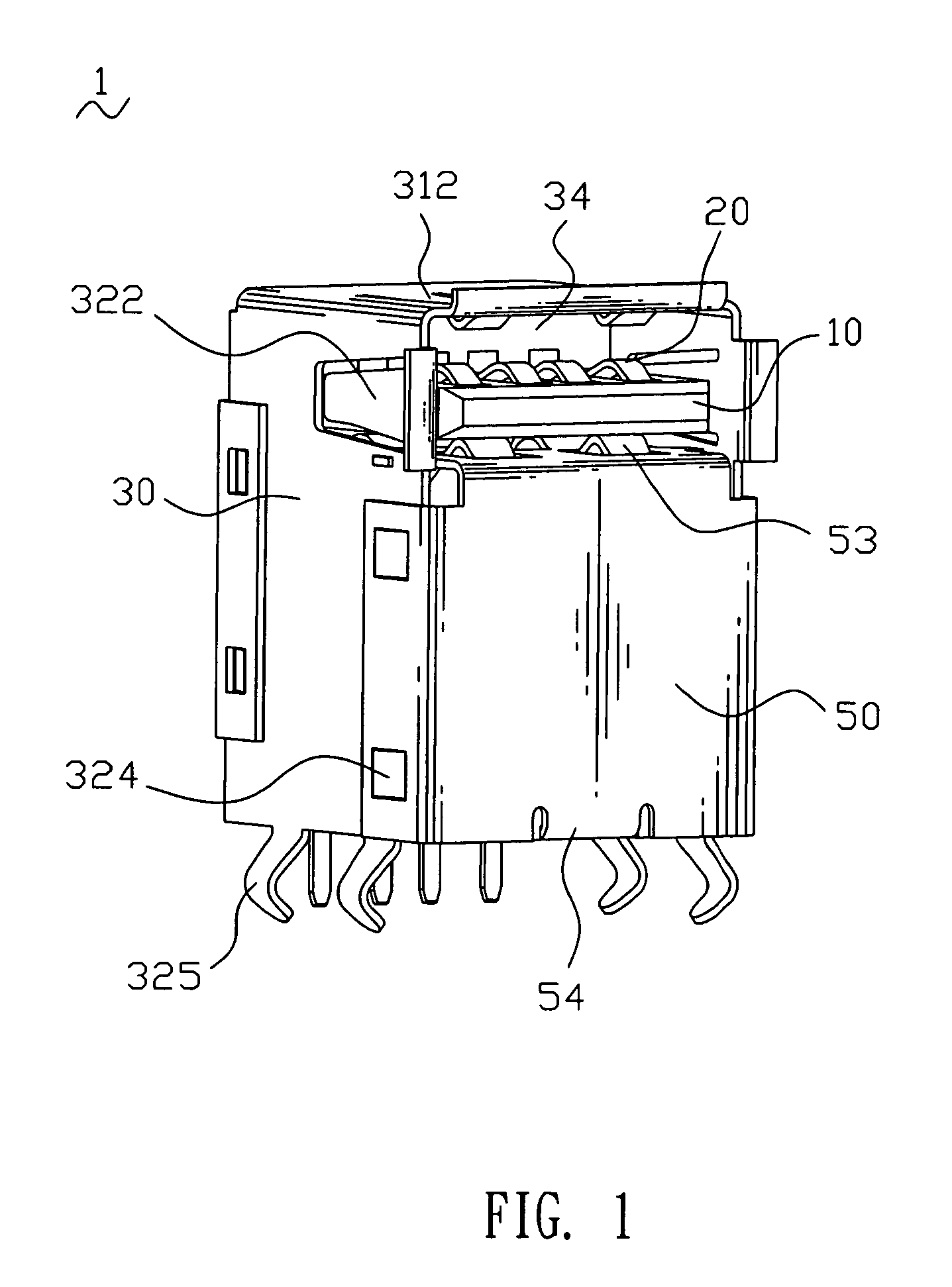
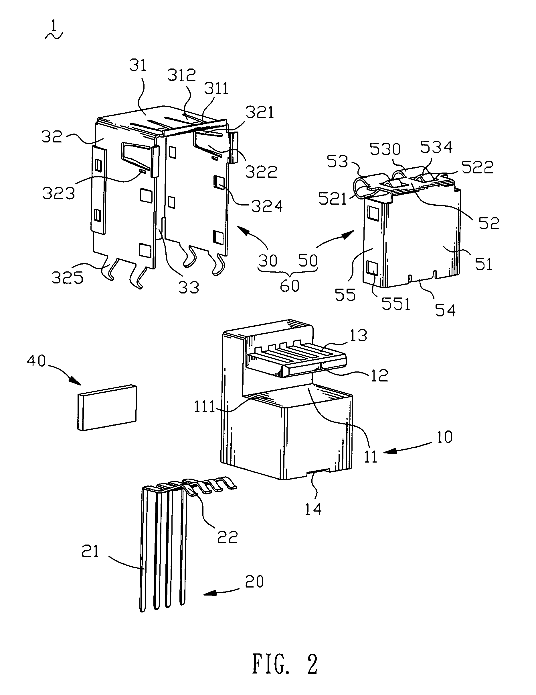
[0013]With reference to FIG. 1 and FIG. 2, an electrical connector 1 of an embodiment according to the present invention is shown. The electrical connector 1 includes an insulating housing 10 of rectangular shape, a plurality of terminals 20 and a shell 60 coupled with the insulating housing 10.

[0014]Please refer to FIG. 2 and FIG. 3, the insulating housing 10, defining a front end and a rear end opposite to the front end, has a recess 11 at an upper portion of the front end thereof. The recess 11 passes through a top surface and two opposite sides of the insulating housing 10, and defines a bottom surface 111. A rear surface of the recess 11 is protruded frontward to form a receiving plate 12, with a width thereof less than a width of the insulating housing 10. The receiving plate 12 has a plurality of terminal grooves 13 extending frontward and rearward and reaching a rear surface of the insulating housing 10 for receiving the terminals 20. The insulating housing 10 has a stopping...


PUM


Abstract

An electrical connector has an insulating housing defining a recess. A receiving plate extends frontward from a rear surface of the recess and spaced apart from a bottom surface thereof. A shell coupled with the insulating housing to form an insertion space where the receiving plate is located has a connecting plate located between the receiving plate and the bottom surface of the recess. A portion of the connecting plate is extended and curved upwards and then curved downwards and upwards sequentially to form a substantial split ring-shaped resilient element. The resilient element comprises an upper resistive portion located adjacent to the receiving plate and a lower resistive portion located adjacent to the bottom surface of the recess. A free end of the lower resistive portion extends obliquely upwardly to form a connecting portion. A distal end of the connecting portion forms a propping portion located above the connecting plate.

Description

BACKGROUND OF THE INVENTION[0001]1. Field of the Invention[0002]The present invention generally relates to a connector, and more particularly to an electrical connector adapted for electrically connecting with a mating plug.[0003]2. The Related Art[0004]A portable electronic device is usually equipped with an electrical connector for electrically connecting with a mating plug, such as a universal serial bus (USB) plug. The conventional electrical connector generally involves an insulating housing, a plurality of terminals mounted in the insulating housing, and a shell coupled with the insulating housing to form an insertion chamber for receiving the USB plug. The shell, as well as we know, is often punched a plurality of buckling tabs. The buckling tabs extend into the insertion chamber to rest against the USB plug resiliently for making the USB plug connect with the terminals steadily. However, with frequent insertion and extraction operation of the USB plug, the resilience of the ...

Claims


Application Information

Patent Timeline
IPC IPC(8): H01R13/648
CPCH01R13/639H01R12/712H01R13/65802H01R13/6582H01R13/658
Inventor YUAN, SHENG-TSUNGPENG, YUNG-CHI
Owner CHENG UEI PRECISION IND CO LTD
Why Eureka
Try Eureka