
3D printing of crystalline polymeric material

Inactive Publication Date: 2021-06-17
INTAMSYS TECH CO LTD
View PDF0 Cites 0 Cited by
  • Summary
  • Abstract
  • Description
  • Claims
  • Application Information

AI Technical Summary

Benefits of technology

The invention provides a 3D printing process that can deposit a solid print pattern of amorphous polymeric material by cooling the molten print pattern, which prevents crystallization and ensures a melting of the crystalline polymeric material when depositing layers. This decreases the energy for bonding the layers, increases flexibility of the printed object, prevents deformation due to stress accumulation, and allows for precise shape of the printed object without bending or breakage. The 3D printer of the invention does not require a closed room or increased temperature of the print head and has a prolonged useful life, decreased energy consumption, and decreased manufacturing cost.

Problems solved by technology

However, the conventional art is disadvantageous because it is very difficult, the elevated room temperature may cause mechanisms and circuitry of the 3D printer to malfunction, reliability is decreased greatly, and useful life of the 3D printer is shortened greatly.
In addition, degree of crystallinity of a 3D-printed object is adversely increased, thereby rendering the 3D-printed object to be more brittle and less flexible.

Method used


Image

  • 3D printing of crystalline polymeric material
  • 3D printing of crystalline polymeric material
  • 3D printing of crystalline polymeric material

Examples


Embodiment Construction

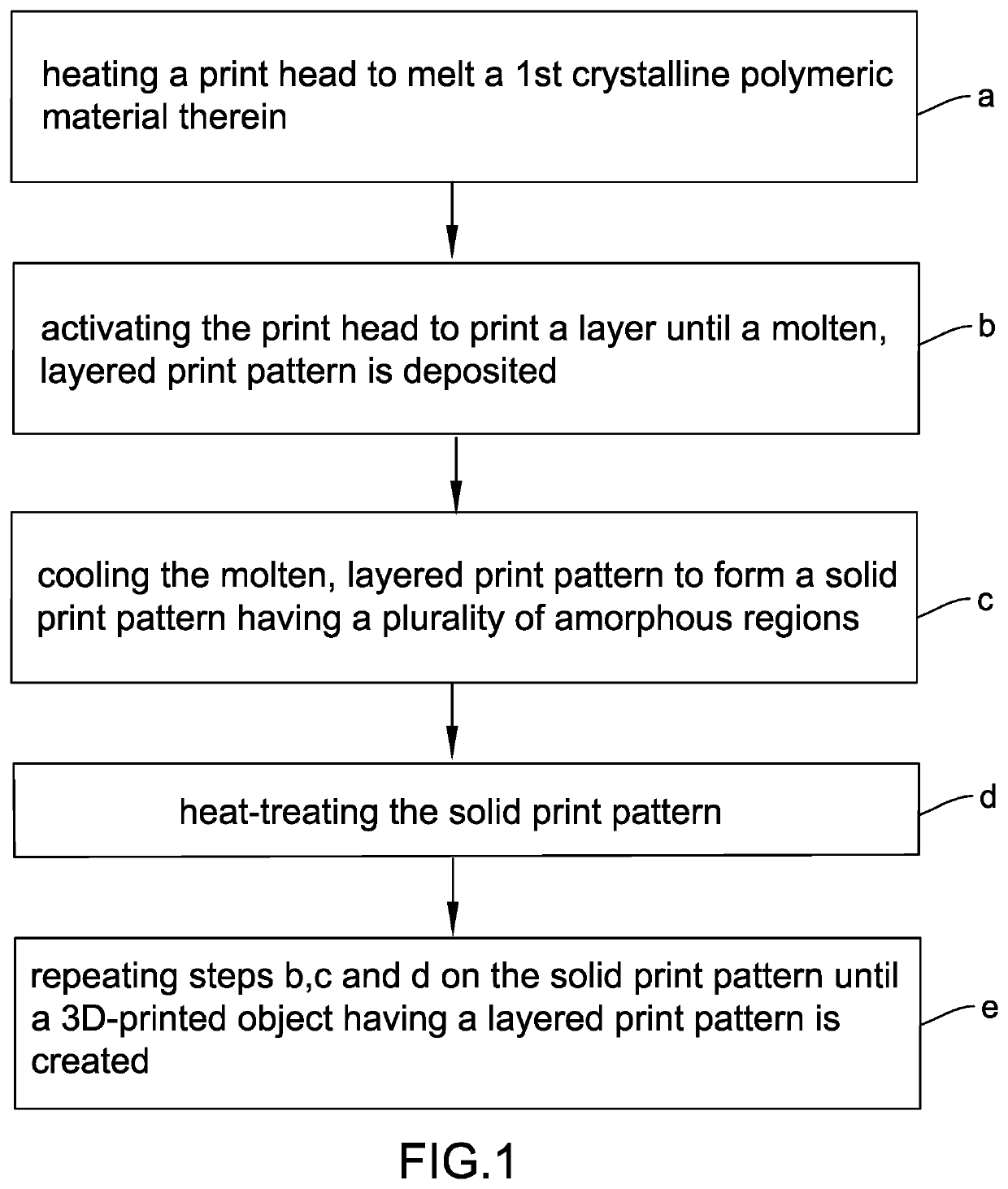
[0023]Referring to FIG. 1, a flow chart of a process of 3D printing of crystalline polymeric material of a preferred embodiment of the invention is illustrated. The process comprises the steps of (a) heating a print head to melt a first crystalline polymeric material therein, (b) activating the print head to print a layer until a molten, layered print pattern is deposited, (c) cooling the molten, layered print pattern to form a solid print pattern having a plurality of amorphous regions, (d) heat-treating the solid print pattern, and (e) repeating steps (b), (c), and (d) until a 3D-printed object having a layered print pattern is created, i.e., successively adding material layer by layer. A print pattern unit includes at least one print pattern layer.

[0024]In one embodiment, the print pattern unit includes a plurality of print pattern layers, and the print pattern layers are layered.

[0025]In one embodiment, the process further comprises obtaining a digital 3D model. The print head s...


PUM

PropertyMeasurementUnit
Thicknessaaaaaaaaaa
Temperatureaaaaaaaaaa
Glass transition temperatureaaaaaaaaaa

Abstract

A process of 3D printing of crystalline polymeric material includes the steps of (a) heating a print head to melt a first crystalline polymeric material therein; (b) activating the print head to print a layer until a molten, layered print pattern is deposited; (c) cooling the molten, layered print pattern to form a solid print pattern having a plurality of amorphous regions; (d) heat-treating the solid print pattern; and (e) repeating steps (b), (c), and (d) until a 3D-printed object having a layered print pattern is created. A print pattern unit includes at least one print pattern layer.

Description

BACKGROUND OF THE INVENTION1. Field of the Invention[0001]The invention relates to three-dimensional (3D) printing and more particularly to a process of 3D printing of crystalline polymeric material and a 3D printer thereof.2. Description of Related Art[0002]3D printing processes are widely employed in many applications due to advancement of 3D printing technologies. A typical 3D-printing process comprises the steps of creating a digital 3D model with a computer-aided design (CAD) package, converts the 3D model into a series of thin layers and produces a file containing instructions tailored to a specific type of 3D printer, and printing the file with 3D printing client software which loads the file and uses it to instruct the 3D printer during the 3D printing process. As a result, a 3D object is created.[0003]Polymeric materials for 3D printing are crystalline polymeric materials or non-crystalline polymeric materials. But crystalline polymeric materials comprise crystalline monome...

Claims


Application Information

Patent Timeline
IPC IPC(8): B29C64/118B33Y10/00B33Y30/00B29C64/295B29C64/209
CPCB29C64/118B33Y10/00B29K2995/0041B29C64/295B29C64/209B33Y30/00B29C64/188
Inventor DONG, XIANMINGHAN, CHENGCHAOQIN, SHAOWU
Owner INTAMSYS TECH CO LTD
Learn More