Electric Motor And Motor Shaft Thereof

Active Publication Date: 2018-06-21
JOHNSON ELECTRIC INTERNATIONAL AG
View PDF6 Cites 0 Cited by
  • Summary
  • Abstract
  • Description
  • Claims
  • Application Information

AI Technical Summary

Benefits of technology

[0018]In the present embodiments, the axial length of the chamfer is greater than the depth of the groove. When mounting a bearing around the motor shaft, the inner race of the bearing can effectively avoid burrs formed on edges

Problems solved by technology

During the chamfered end 11 of the motor shaft extending through the bearing, burrs existed at the edge of the groove 112 and non-circular cross section structure of the chamfered end 11 due to forming the groove 11

Method used


Image

  • Electric Motor And Motor Shaft Thereof
  • Electric Motor And Motor Shaft Thereof
  • Electric Motor And Motor Shaft Thereof

Examples


Example

[0025]Below, embodiments of the present invention will be described in greater detail with reference to the drawings. Apparently, the described embodiments are merely part of, rather than all of, the embodiments of the present invention. Based on the described embodiments of the present invention, any other embodiment obtained by a person skilled in the art without paying creative efforts shall also fall within the scope of the present invention.

[0026]Unless otherwise specified, all technical and scientific terms used in this disclosure have the ordinary meaning as commonly understood by people skilled in the art. The terms used in the specification of this disclosure are only for illustrating embodiments of the disclosure and do not limit the scope of the present disclosure.

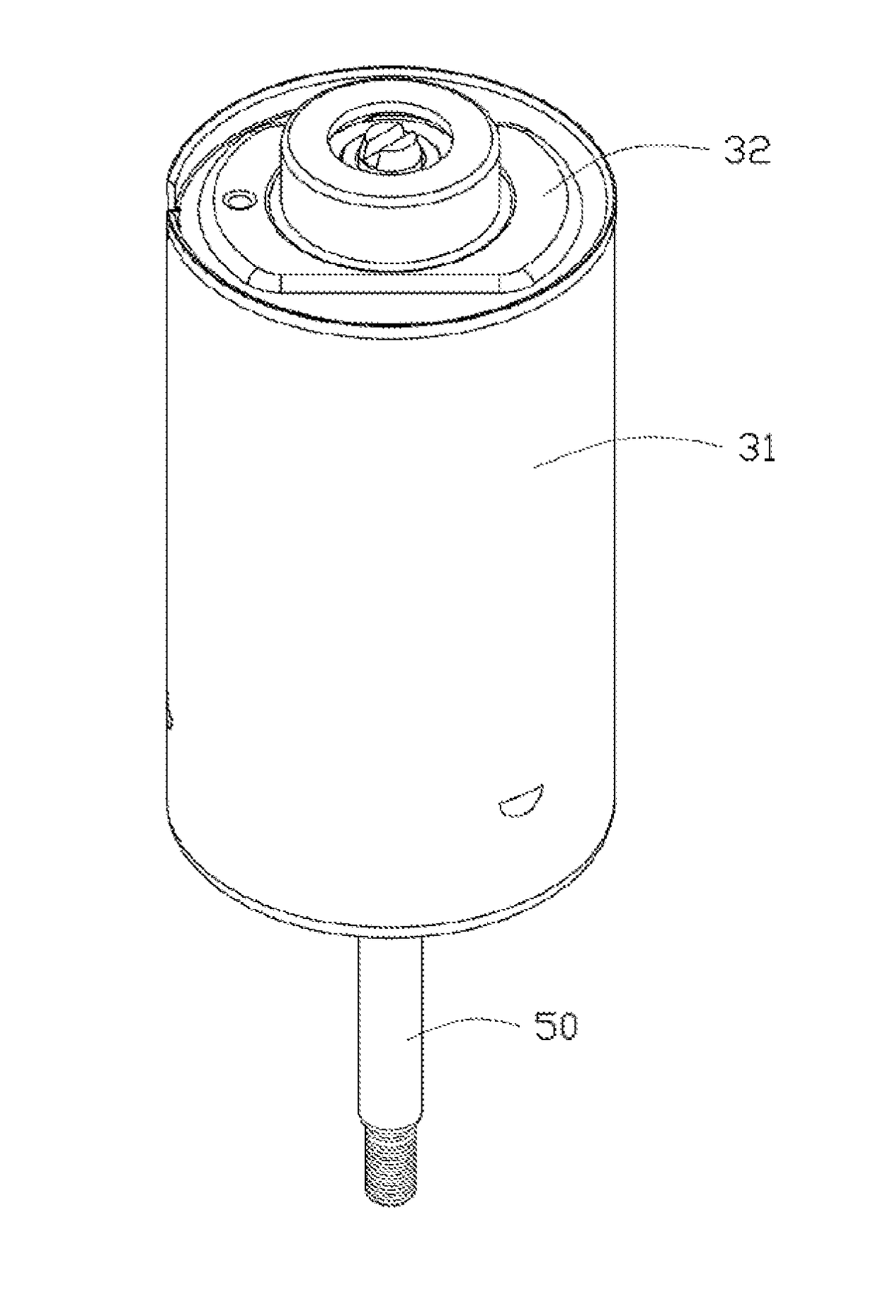
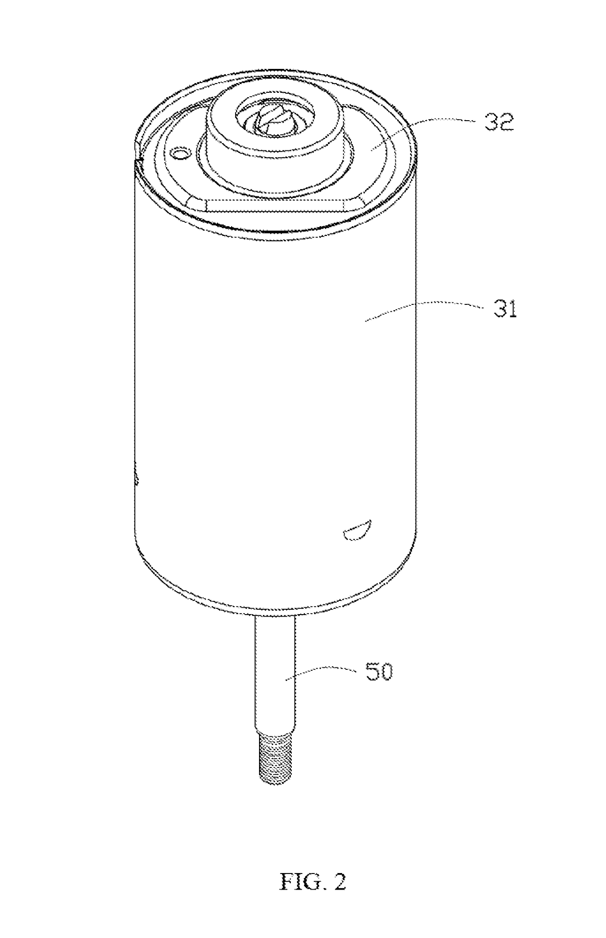
[0027]FIG. 2 is a perspecitve view of an electric motor according to an embodiment of the present disclosure. FIG. 3 is an exploded view of the electric motor of FIG. 2. Referring to FIGS. 2-3, the electric moto...


PUM


Abstract

A motor shaft includes a main body and a chamfered end formed at an end of the main body. The chamfered end has a chamfer formed at a peripheral surface thereof, and a groove defined in an end surface thereof. An axial length of the chamfer is greater than a depth of the groove in the axial direction of the motor shaft. An electric motor including the motor shaft is also provided.

Description

CROSS REFERENCE TO RELATED APPLICATIONS[0001]This non-provisional patent application claims priority under 35 U.S.C. § 119(a) from Patent Application No. 201611170866.2 filed in The People's Republic of China on Dec. 16, 2016.FIELD OF THE INVENTION[0002]The present invention relates to the field of motors, and in particular to a motor shaft and an electric motor using the motor shaft.BACKGROUND OF THE INVENTION[0003]Electric motor that converts electric energy into mechanical energy, is used in every field of production and life of human. A motor shaft is one of the main parts of a motor. The output end of the motor shaft which extends to outside of the motor is used to connect with a load driven by the motor, such as a gear, a fan or a belt pulley. FIG. 1 is a perspective view of a traditional motor shaft. The motor shaft has opposite two ends, i.e., a threaded end 10 and a chamfered end 11. The chamfered end 11 includes a chamfer 111 and an elongated groove 112 defined in the end ...

Claims


Application Information

Patent Timeline
IPC IPC(8): H02K7/00H02K7/08
CPCH02K7/003H02K7/08F16C3/02H02K7/083
Inventor KEIL, RONNYTSUNASHIMA, DAISUKEPOON, KWONG YIPSONG, YONGQIANG
Owner JOHNSON ELECTRIC INTERNATIONAL AG
Why Eureka
Try Eureka