Coupling wire guide

a wire guide and wire guide technology, applied in the field of wire guides, can solve the problems of proximal tortuosity of the vasculature being problematic, the tip of the wire guide may prolapse away from the site, and the wire guide is subject to potentially conflicting requirements, so as to achieve easy and reliable traversal through the vasculature

Active Publication Date: 2010-06-08
COOK MEDICAL TECH LLC
View PDF126 Cites 28 Cited by
  • Summary
  • Abstract
  • Description
  • Claims
  • Application Information

AI Technical Summary

Benefits of technology

[0008]The present invention provides a supporting wire guide for intracorporeal procedures that may be easily and reliably traversed through the vasculature to a position proximate a previously introduced wire guide. The supporting wire guide is a coupling wire guide that is structured to be slidably coupled to the previously introduced wire guide. In one embodiment constructed in accordance with the teachings of the present invention, the coupling wire guide generally includes a main body having a distal section. The distal section includes an outer wire disposed over a safety wire. A loop wire is connected to the safety wire at two axially spaced points. At least a portion of the loop wire is positioned outside of the outer wire to define a loop area sized to receive the previously introduced wire guide.

Problems solved by technology

Proximal tortuosity of the vasculature is problematic for all medical catheter devices such as atherectomy devices, angioplasty devices, stent delivery devices, and filter delivery devices.
Accordingly, wire guides are subjected to potentially conflicting requirements.
However, in some situations the wire guide tip may prolapse away from the site to which it is guiding the device.
For example, balloon angioplasty in vessels with proximal tortuosity has been associated with a higher incidence of acute complications and procedural failure due to the inability to cross lesions with a conventional floppy wire guide, and due to the inability of the wire guide to provide adequate support to the balloon catheter.
Heavy-duty wire guides, on the other hand, are generally not well suited as primary wire guides because of their stiffness and potential for causing injury to the vessel during introduction.
However, the navigation of the supplemental wire guide parallel to the first wire guide is an exacting and time consuming process in which additional difficulties are encountered.
For example, the second wire guide can cork screw or coil around the first wire guide, which may result in immobilization or unintended movement of the first wire guide, which in turn may require the retraction and re-feeding of the supplemental wire guide and / or the primary wire guide.
Moreover, if retraction of the supplemental wire guide is necessary, either of the wire guides may become contaminated and the entire process may need to be restarted with sterile components.
Additionally, when traversing through the heart of a patient, and particularly the ostium, the larger open space of the heart makes identical placement of the supplemental wire guide somewhat difficult.

Method used


Image

  • Coupling wire guide
  • Coupling wire guide
  • Coupling wire guide

Examples


Embodiment Construction

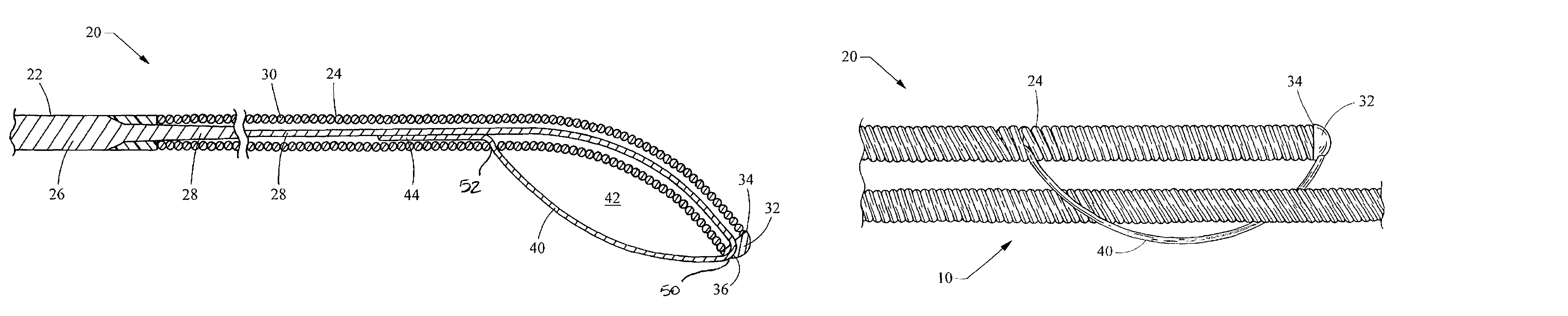
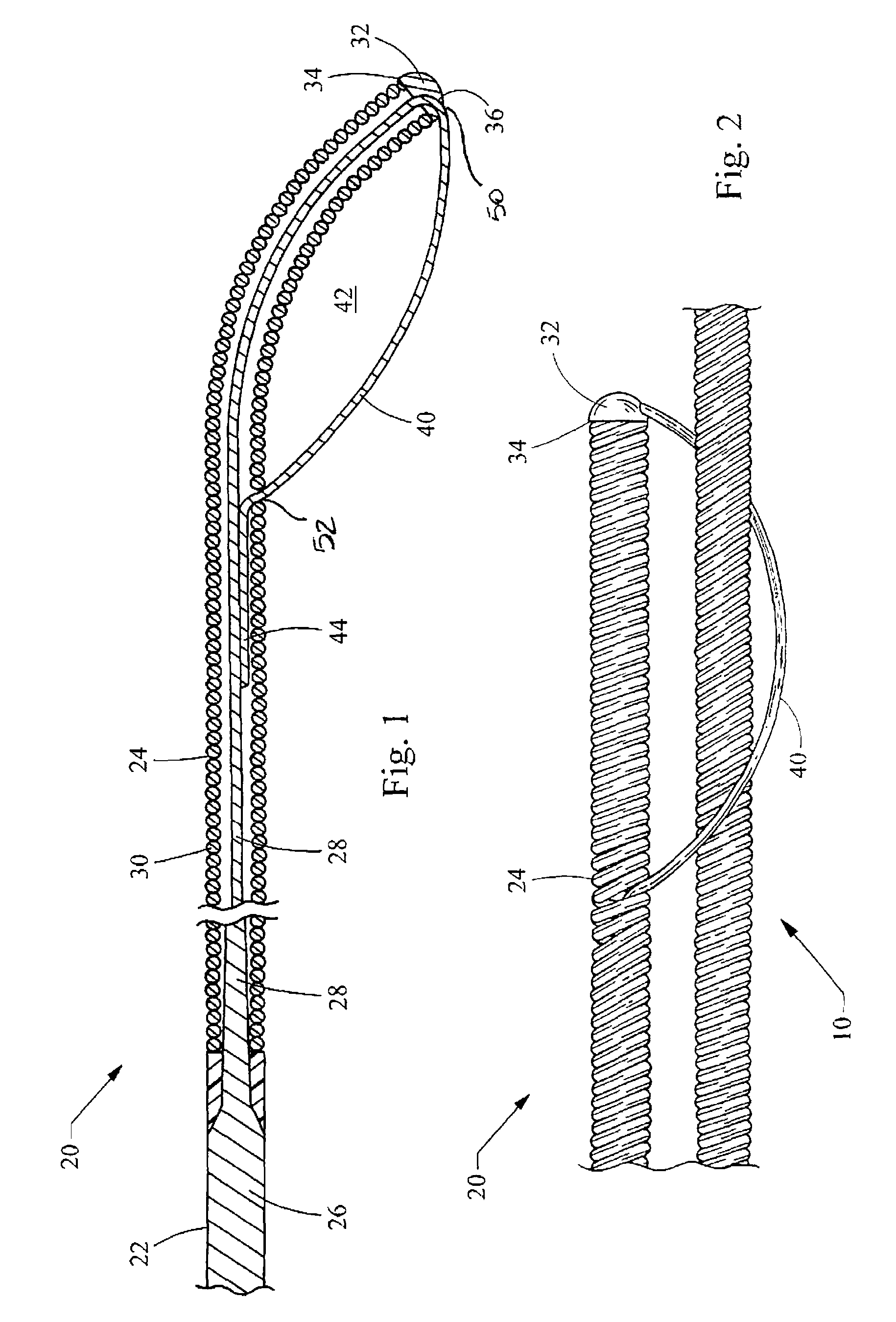
[0015]Turning now to the figures, FIGS. 1 and 2 depict a coupling wire guide 20 constructed in accordance with the teachings of the present invention. The coupling wire guide 20 includes a main body 22 having a distal section 24. The main body 22 has been shown as a mandrel 26, a structure well known in the art. In the area of the distal section 24, the mandrel 26 narrows to define a safety wire 28 over which an outer wire 30 is disposed. Specifically, the outer wire 30 is coiled over the safety wire 28, which in turn is connected to an end cap 32 to define a distal tip 34 of the coupling wire guide 20.

[0016]The coupling wire guide 20 is structured for coupling to a previously introduced wire guide, which is depicted in FIG. 2 as a coiled wire 10. It will be recognized that the previously introduced wire guide 10, as well as the main body 22 of the coupling wire guide 20, may take numerous forms as many types of wire guides are known in the art, including a solid wire, tubular wires...


PUM


Abstract

A coupling wire guide structured to be slidably coupled to a previously introduced wire guide. The coupling wire guide includes a main body having a distal section. The distal section includes an outer wire disposed over a safety wire. A loop wire is connected to the safety wire at two axially spaced points. At least a portion of the loop wire is positioned outside of the outer wire to define a loop area sized to receive the previously introduced wire guide.

Description

CROSS-REFERENCE TO RELATED APPLICATIONS[0001]This application claims the benefit of U.S. Provisional Application Ser. No. 60 / 730,582 filed on Oct. 27, 2005, entitled “COUPLING WIRE GUIDE”, the entire contents of which are incorporated herein by reference.FIELD OF THE INVENTION[0002]This invention relates generally to a wire guide for use in intracorporeal procedures, and more particularly relates to the construction of a wire guide to be coupled to a previously introduced wire guide for assistance during interventional procedures in vessels with proximal tortuosity, or as a more substantial wire guide for angioplasty procedures, stenting procedures, and other device placement procedures and their related devices.BACKGROUND OF THE INVENTION[0003]Proximal tortuosity of the vasculature is problematic for all medical catheter devices such as atherectomy devices, angioplasty devices, stent delivery devices, and filter delivery devices. Wire guides are therefore typically used to navigate...

Claims


Application Information

Patent Timeline
Patent Type & Authority Patents(United States)
IPC IPC(8): A61M5/178A61B17/24A61B17/26A61M25/00
CPCA61M25/09A61M25/0905A61B2017/003A61B2017/22042A61M2025/09066A61B2017/2212
Inventor MELSHEIMER, JEFFRY S.
Owner COOK MEDICAL TECH LLC
Why Eureka
Try Eureka